18
Interrupter/Operator Description
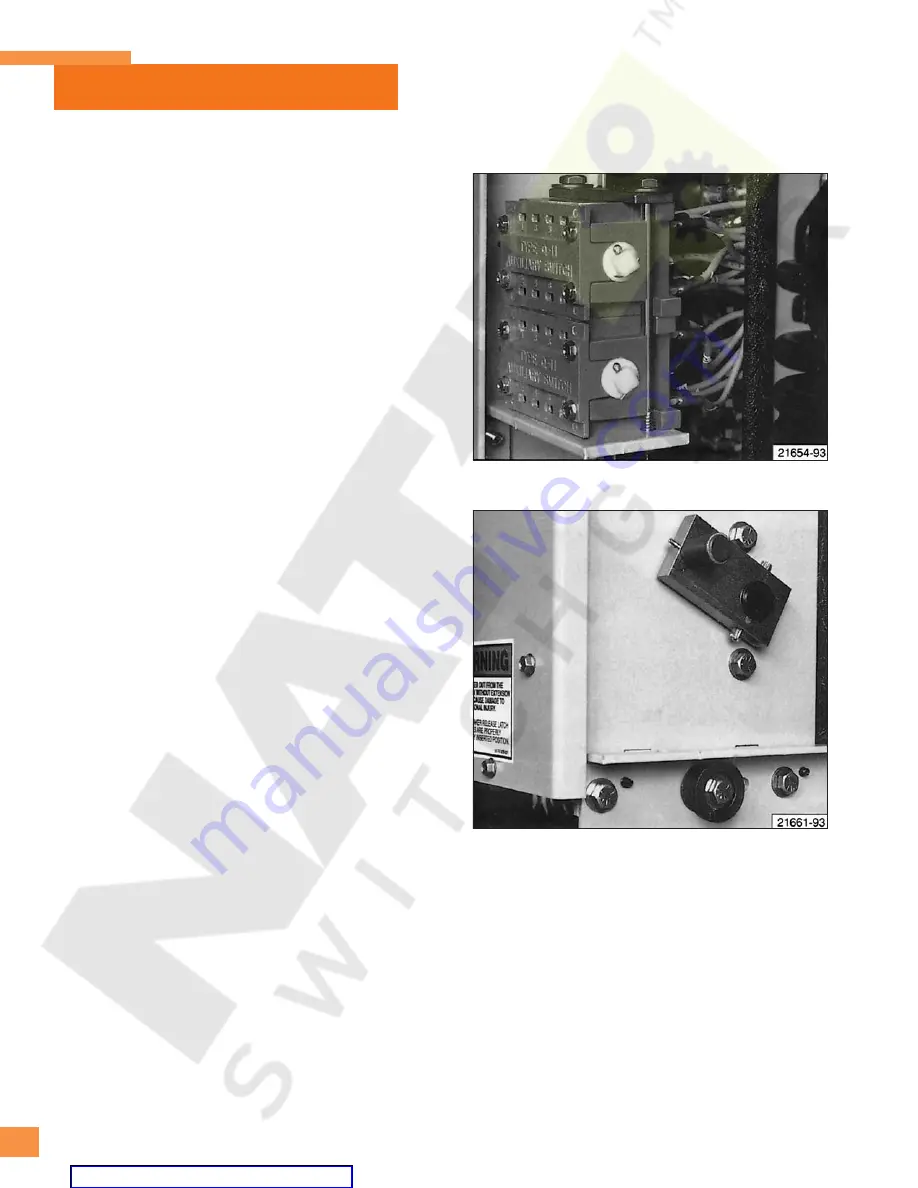
Figure 25:
MOC Switch Operating Arm on Circuit Breaker.
Figure 24:
Auxiliary Switch.
by the close solenoid can occur during each application of
the close command. The circuit breaker must be tripped,
the springs recharged and the closing signal removed (inter-
rupted) before the close solenoid can be energized the
second time.
When the trip solenoid is energized, it allows rotation of the
jack shaft by the tripping spring. This rotation pulls the insu-
lating push rods attached to the movable contacts of the
three vacuum interrupters, and the circuit breaker contacts
are opened.
Electrical connections to the close solenoid and trip
solenoid are made through quick disconnect terminations.
Secondary Disconnect
Signal and control power is delivered to the internal circuits
of the circuit breaker by an arrangement of movable contact
fingers mounted on the left side of the circuit breaker.
These fingers are shown in
Figure 22
.
When the circuit breaker is racked into the Test or
Connected positions in the metal-clad switchgear, these
disconnect fingers engage a mating disconnect block on the
inside of the switchgear shown in
Figure 23
. These elec-
trical connections automatically disengage when the circuit
breaker is racked from the Test to the Disconnect position.
All of the control power necessary to operate the circuit
breaker is connected to the disconnect block inside the
switchgear. The external trip and close circuits and status
indicators are also connected to this same disconnect block.
Auxiliary Switch
Figure 24
shows the circuit breaker mounted auxiliary
switch. This switch provides auxiliary contacts for control of
circuit breaker closing and tripping functions.Contacts are
available for use in relaying and external logic circuits. This
switch is driven by linkages connected to the jack shaft. The
auxiliary switch contains both ‘b’ (Normally Closed) and ‘a’
(Normally Open) contacts. When the circuit breaker is open,
the ‘b’ switches are closed and the ‘a’ switches are open.
MOC (Mechanism Operated Cell) Switch
Figures 25
and
26
show the principal components that
provide optional control flexibility when operating the
circuit breaker in the Test and Connected positions.
Figure 25
shows the MOC switch operating arm that
projects from the right side of the circuit breaker, just above
the bottom rail structure. The MOC switch operating arm is
part of the jack shaft assembly, and directly reflects the
open or closed position of the circuit breaker primary
contacts.
As the circuit breaker is racked into the appropriate position
inside the switchgear, the MOC switch operating arm passes
a wiring protective cover plate, and engages the pantograph
linkage shown in
Figure 26
. Operation of the circuit
breaker causes the pantograph linkage to transfer motion
to the MOC switches located above the pantograph. The ‘a’
and ‘b’ contacts can be used in relaying and control logic
schemes.
All circuit breakers contain the MOC switch operating arm.
However, MOC switches are provided in the switchgear
only when specified.
The circuit breaker engages the MOC auxiliary switch only
in the connected (operating) position unless an optional
test position pickup is specified in the contract. If a test
position pickup is included, the circuit breaker will engage


