Cold room gate drive ATD400K
32
A2B00101049-01, 08/2012
7
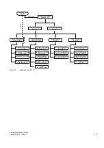
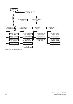
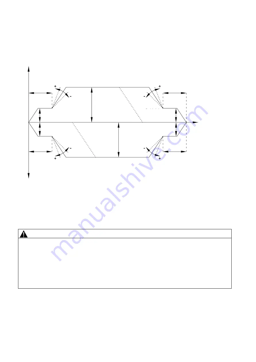
Travel curve
Travel curve
Speed
OPEN
Speed
CLOSE
Cutter
distance
OPEN
Acceleration
ramp OPEN
Reverse ramp
Brake ramp
OPEN
Creep distance
OPEN
V
max
OPEN
Cutter speed
OPEN
Cutter
distance
CLOSE
Brake ramp
CLOSE
Reverse ramp
CLOSE_OPEN
Acceleration ramp
CLOSE
Creep distance
CLOSE
Route
Creep speed
OPEN
Creep speed
CLOSE
Cutter speed
CLOSE
V
max
CLOSE
Figure 7-1
Travel curve
Reversing ramp OPEN_CLOSE = direction of travel reverses from
OPEN
to
CLOSE
. Reversing ramp CLOSE_OPEN =
direction of travel reverses from
CLOSE
to
OPEN
.
When reversing from the opening direction to the closing direction, the cold room gate is braked with the reversing ramp
OPEN_CLOSE, and starts the closing movement with the acceleration ramp CLOSE.
WARNING
Risk of injury from moving mechanical parts
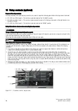
After the cold room gate has been commissioned in the entire cold room gate system, arrange for the forces and energies
to be checked by the service personnel, and adjusted if they exceed their limiting values. The following guidelines must be
observed:
●
The speed limit curve is the characteristic curve which defines the maximum permissible gate speed V
max
as a function
of the total gate panel weight. According to EN 81, the maximum kinetic energy of the cold room gate in the closing
direction must not exceed 10 joules.
●
According to EN 81, the maximum kinetic energy must not exceed 4 joules while the reversing device is switched off.
●
Gearing up or down is not allowed on the toothed belt because this would change the kinetic energies or static forces
on the cold room gate. The gate width would then no longer be valid.

