Controllers
4.4 Connecting terminals
ATD4xxW Door Controller for Industrial Applications
108
System Manual, 01/2017, A5E38080677-AB
4.4
Connecting terminals
4.4.1
Digital input signals
Slot X6
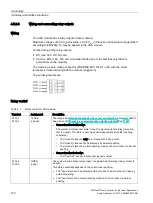
You can connect certain signals for drive functions at the inputs Input 1, Input 2, Input 3,
Input 4 (X6) and Input 0 (X5). The following table shows how the drive function and input are
assigned depending on the controller.
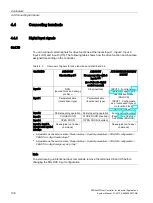
Table 4- 2
Overview of signals for drive functions at slots X5 and X6
Slot X5/X6
ATD401W
Standard input
1)
ATD401W
Emergency stop with 3
inputs
2) 3)
(see Fail-safe digital
control concept)
ATD410W/ATD420W/AT
D430W
Input 0
NDG
(second force and energy
profile)
3)
Stop (inverted)
INPUT 0: Functions con-
free function blocks
(FBLOCK)
INPUT 1: Configurable
as a local sensor type or
via function blocks
Input 1
Parameterizable
(local sensor type)
Parameterizable
(local sensor type)
Input 2
Partial opening operation Partial opening operation Functions configurable
(Page 71) via free func-
tion blocks (FBLOCK)
Input 3
CLOSE DOOR
CLOSE DOOR (inverted)
Input 4
OPEN DOOR
OPEN DOOR (inverted)
Input 1, Input 2,
Input 3 and Input 4
inactive
Deenergize (not a door
command)
–
Deenergize (not a door
command)
1)
Adjustable via the service menu
"General setup > Special parameters > FBLOCK configuration >
FBLOCK config. Standard input"
2)
Adjustable via the service menu
"General setup > Special parameters > FBLOCK configuration >
FBLOCK config. Emergency stop 3 inp."
Note
To avoid issuing unintentional door commands, remove the terminals X6 and X5 before
changing the FBLOCK input configuration.
Summary of Contents for SIDOOR ATD401W
Page 1: ......

