Controllers
4.4 Connecting terminals
ATD4xxW Door Controller for Industrial Applications
110
System Manual, 01/2017, A5E38080677-AB
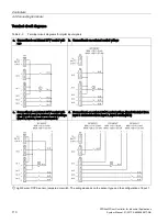
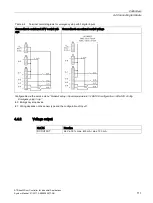
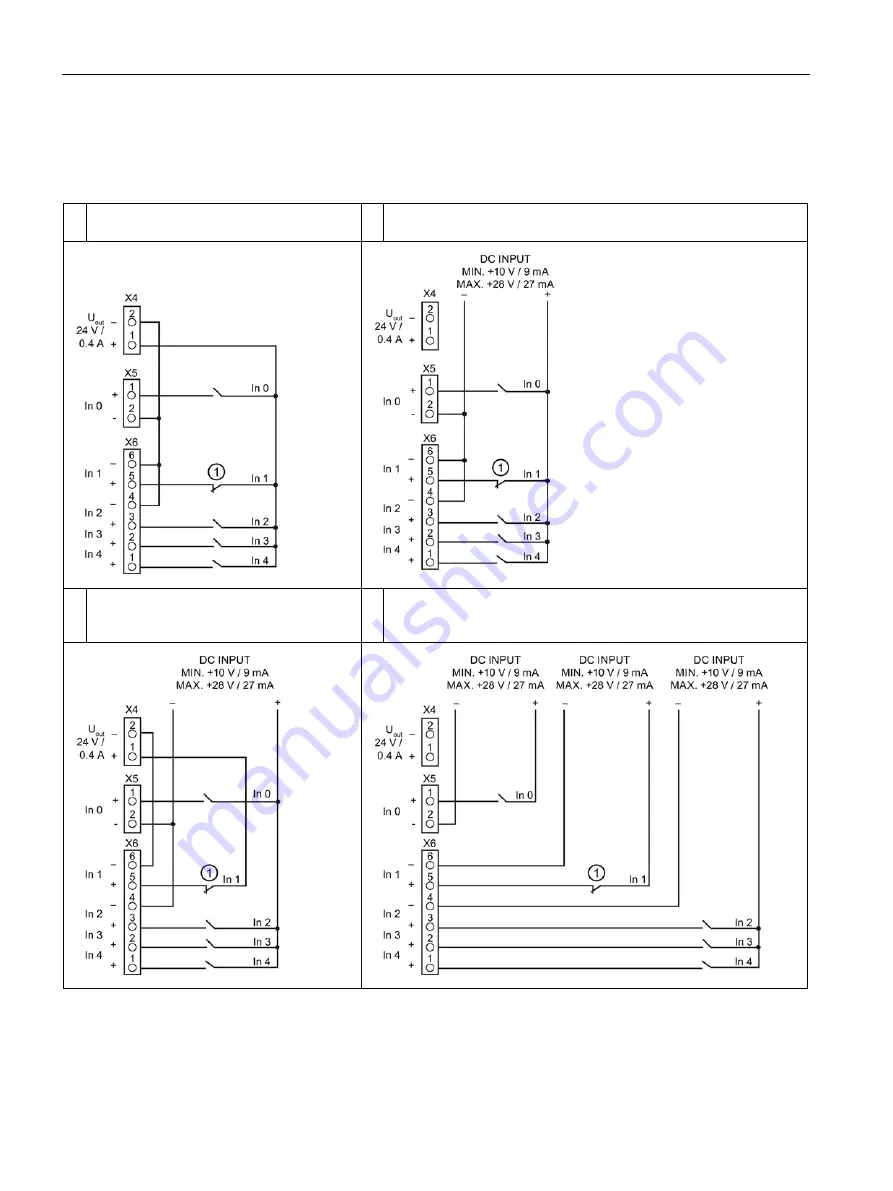
Terminal circuit diagrams
Table 4- 3
Terminal circuit diagrams for digital input signals
a. Connection to an internal 24 V control volt-
age
b. Connection to an external control voltage
c. Connection to an internal 24 V control volt-
age (input 1) and an external control voltage
(input 0, input 2, input 3 and input 4)
d. Connection to an external 24 V control voltage (input 0 isolated from
input 1 and isolated from input 2, input 3 and input 4)
①
Light barrier, DCPS sensor, jumpered or switch. The wiring depends on the sensor type and the configuration of Input 1.
Summary of Contents for SIDOOR ATD401W
Page 1: ......


