Controllers
4.5 Relay and fieldbus interfaces
ATD4xxW Door Controller for Industrial Applications
146
System Manual, 01/2017, A5E38080677-AB
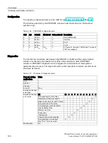
Configuration
The resulting configuration data is in the GSD file (see Table 4-17 GSD files (Page 136)).
The structure expected by the PROFINET module is described below (for informational
purposes only):
Table 4- 26 PROFINET configuration data
Slot Api
Subslot
Module ID Submodule ID Description
0
0
0001
hex
1
1
DAP (ATD430W)
0
0
8000
hex
1
2
Interface
0
0
8001
hex
1
3
Port 1
0
0
8002
hex
1
3
Port 2
1
0
0001
hex
28
hex
1
22 bytes IO (4 words of PKW and 7 words of
PZD are mapped)
Diagnostics
The internal communication bus between the SIDOOR controller and the communication
module is monitored by the master driver of the communication module (PROFINET
module). A PROFINET diagnostic alarm is triggered if communication is interrupted or
quality becomes too poor. This diagnostic alarm is then present for at least 5 seconds and is
structured as follows:
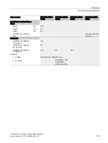
Table 4- 27 Properties of diagnostic alarm
Property of diag-
nostic alarm
Value
Slot
1
Subslot
1
Channel
1
Error ID
1B
hex
Extended channel
error type
1
Extended channel
error value
Bit
10 9 8 7 6 5 4 3 2 1 0
Telegram length (LGE) false
X
Remaining runtime exceeded
X
Block check character (BCC) false
X
Telegram start (STX) false
X
Telegram type unknown (ADR)
X
Slave address false
X
Memory overflow
X
Parity error
X
Internal error
X
Answer delay time exceeded
X
Telegram type not identical
X
Bits 15 to 11 are reserved.
Maintenance
No
Summary of Contents for SIDOOR ATD401W
Page 1: ......

