Appendices
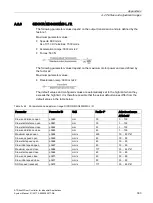
A.1 Structure of user data/process data
ATD4xxW Door Controller for Industrial Applications
System Manual, 01/2017, A5E38080677-AB
289
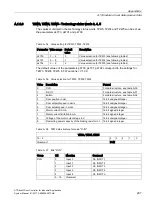
A.1.2.4
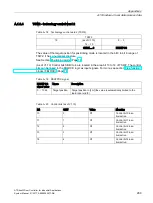
TSW2 - technology control word 2
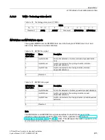
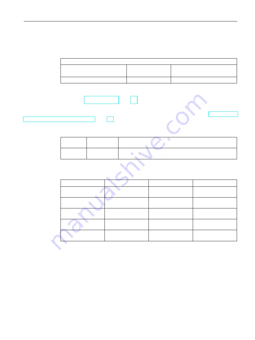
Table A- 18 Technology control word 2 (TSW2)
TSW2
15
(as of V1.10)
14 ... 10
9 … 0
SBIT4 ... 0
DESTPOS
The value of the target position for positioning mode is located in the bit 0 to bit 9 range of
TSW2. It has a numerical structure.
See Section Positioning mode (Page 70).
(As of V1.10) Control bits SBit0 to 4 are located in the area bit 10 to 14 of TSW2. The control
bits can be linked to the FBLOCK logic as input signals. For more, see section Free function
blocks (FBLOCK) (Page 76)
Table A- 19 DESTPOS signal
DESTPOS
signal value
Name
Description
0 … 1024
Target position Target position in [cm] (the value is automatically limited to the
learnt door width)
Table A- 20 Control bits (as of V1.10)
Bit
SBIT
Value
Meaning
10
0
0/1
Control bit 0 inac-
tive/active
11
1
0/1
Control bit 1 inac-
tive/active
12
2
0/1
Control bit 2 inac-
tive/active
13
3
0/1
Control bit 3 inac-
tive/active
14
4
0/1
Control bit 4 inac-
tive/active
Summary of Contents for SIDOOR ATD401W
Page 1: ......

