SIDOOR functions
3.4 Safety functions
ATD4xxW Door Controller for Industrial Applications
System Manual, 01/2017, A5E38080677-AB
91
3.4.2.3
Safe input signals according to PLd
SIDOOR ATD4xxW controllers have five digital inputs (see Digital input signals (Page 108)),
through which safety-related signals can also be sent. This section describes two different
methods for transferring safety-related signals to the controller.
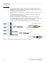
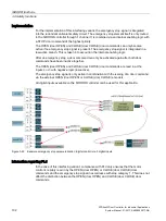
Two concepts are also presented for two-hand operation and emergency stop applications.
The concepts described in this section for implementing safe input signals according to PLd
(Performance Level d) enable detection of the following faults:
●
Discontinuity of one single terminal
●
Short-circuit between any two terminals
●
Stuck-at fault (short-circuit to 1 and 0 in the case of an isolated input or an interrupted
output)
●
Static signal "0" and "1" at all inputs and outputs, individually or simultaneously
●
Parasitic oscillation of outputs
●
Modification of characteristic values (e.g. input/output voltage of analog devices)
3.4.2.4
Internal signal routing
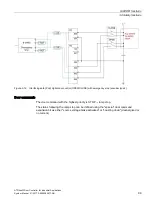
The following figure illustrates the input terminals and the internal wiring to the processor.
The input signals are located at processor port M. Separate reference potentials 0M, 1M and
2M can each be defined for Input 2, Input 3, Input 4 and for Input 1 and Input 0. The input
signals are provided with internal pull-ups and there are no components between the input
terminals and the processor that are capable of oscillation.
①
No components capable of oscillation and internal pull-up circuit
0M Ground potential 1
1M Ground potential 2
2M Ground potential 3
Figure 3-11 Internal wiring of input terminals
Summary of Contents for SIDOOR ATD401W
Page 1: ......


