Controllers
4.9 Operation and configuration of the control unit
ATD4xxW Door Controller for Industrial Applications
184
System Manual, 01/2017, A5E38080677-AB
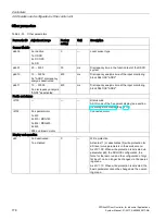
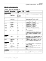
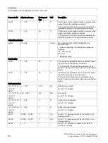
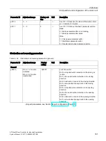
Parameter ID
Adjustment range
Factory setting Unit
Description
Reversing
p3881
0 to 0xFFFF
0 ≙ no reve
rsing
0xFFFF ≙ unl
imited
reversing
0
1 (V1.03 and
higher)
—
Number of reverses
p3882
0 … 60000
2000
ms
Wait time before each reverse
p3883
0 … 60000
0 ≙ full reve
rse
0
200 (V1.03
and higher)
mm
Reversing distance
p3884
0 ≙ deenergize
1 ≙ stop
2 ≙ open
3 ≙ close
0
—
Drive control for obstruction while reversing
p3885
0 ≙ deenergize
1
≙
stop
2 ≙ open
3 ≙ close
0
—
Drive control after all reverses have been execut-
ed
1)
Expert parameters, see Section Expert configuration (Page 75).
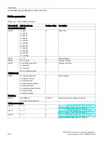
FBLOCK parameters
FBLOCK-DCMD parameters
Drive orders can be assigned to the "Q" outputs with the following FBLOCK-DCMD
parameters. A drive order only becomes active if the assigned output "Q" is active (positive
logic). In the case of edge-controlled signals, the output signal is active for one cycle only.
This is why a correspondingly assigned drive order is latched automatically.
You will find details of the functions and logic of the individual function blocks in Section Free
function blocks (FBLOCK) (Page 76).
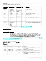
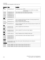
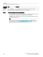
Table 4- 39 FBLOCK-DCMD parameters
Parameter
ID
Name
Description
Digital Input
p20000
DCMD_DI0_Q2
Rising (positive) edge
Output becomes active for one cycle when input edge
detected.
The entered drive order (DCMD) is latched (stored)
automatically.
p20001
DCMD_DI0_Q3
Falling (negative) edge
p20002
DCMD_DI0_Q4
Level-controlled output; output follows the input directly
p20003
DCMD_DI1_Q5
Rising (positive) edge
Output becomes active for one cycle when input edge
detected.
The entered drive order (DCMD) is latched (stored)
automatically.
p20004
DCMD_DI1_Q6
Falling (negative) edge
Summary of Contents for SIDOOR ATD401W
Page 1: ......


