Controller
6.6 Connecting terminals and interfaces
ATE500E
62
System Manual, 09/2017, A5E33917696-AD
6.6.2
Digital input signals
Slot X6
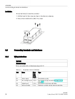
You can connect the following signals for drive functions of the ATE500E controller to the
LIGHT BARRIER / DCPS, NUDGING, CLOSE and OPEN inputs of the terminal X6:
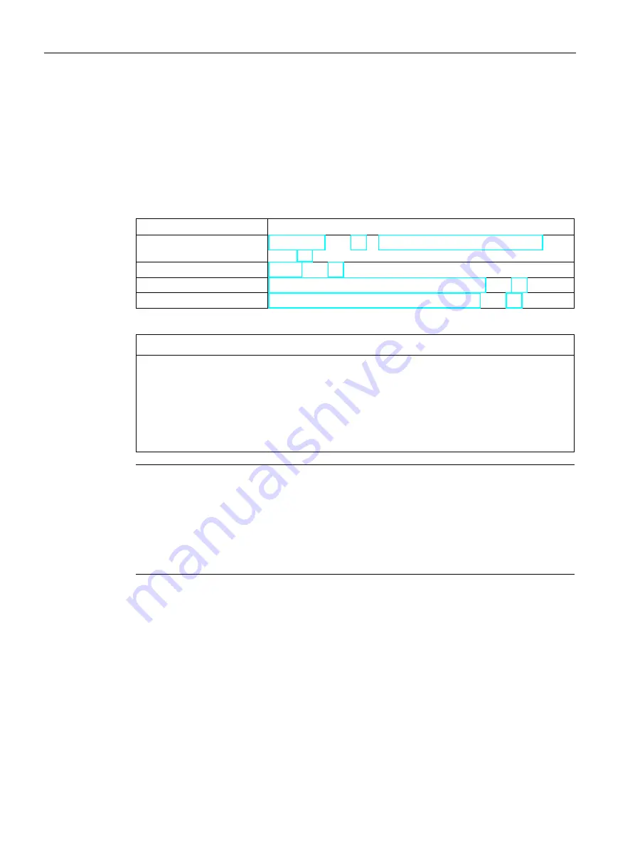
Table 6- 7
Overview of signals for drive functions at slot X6
Slot X6
Drive functions
LIGHT BARRIER / DCPS
Light barrier (Page 24) or DCPS (Door Closed Position Sensor)
(Page 25)
NUDGING
CLOSE
DOOR CLOSE (command given via digital inputs) (Page 27)
OPEN
DOOR OPEN (command given via digital inputs) (Page 28)
NOTICE
Settings required if the LIGHT BARRIER / DCPS input is not used
The following settings must be made if the LIGHT BARRIER / DCPS input is not used for
the light barrier or the DCPS:
•
X6 must be wired to X4 as shown in the following connection diagram, and there must
be a jumper on the light barrier signal (
①
).
•
The LIGHT BARRIER / DCPS input must be configured as "inactive".
Note
The LIGHT BARRIER / DCPS input is electrically isolated from the NUDGING, CLOSE and
OPEN inputs. The LIGHT BARRIER / DCPS input is therefore able to be connected
independently of the NUDGING, CLOSE and OPEN inputs as follows:
1.
Connection to the internal 24 V control voltage (see figures a and c below.)
2.
Connection to the same or a different external control voltage than the NUDGING,
CLOSE and OPEN inputs (see figures b and d below.)


