Siemens Energy & Automation, Inc.
Ground or case internal insulation . . . . . . . . . .2500V AC rating
SCR reverse blocking voltage . . . . . . . . . . . .rating 1300V peak
SCR forward off state voltage . . . . . . . . . . .rating 1300V peak
Reverse leakage current and
forward off state leakage
current at room temperature
and operating voltage levels . . . . . .less than one milliamp
Gate junction typical resistance
range as measured with
typical multimeter ohms scales . . . .10 ohms to 50 ohms
Gate trigger voltage to switch on . . . . . . . . . . . . . . . . . .2V DC
Gate trigger current to switch on . . . . . . . . .100 milliamps DC
Anode circuit holding and
latching currents . . . . . . . . . . . . .300 milliamps to 1 amp
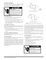
9.4.3 Basic SCR Tests
Make sure all power sources are disconnected from controller
and locked out before performing the following test. See fig-
ures 18 through 20.
Test 1 - Verify Gate Integrity
1. Disconnect gate circuit wires only from each gate terminal.
2. Use a multimeter to measure each SCR gate junction resis-
tance.
3. Connect one meter lead to gate terminal ‘TG.’
4. Check gate resistance both to power cathode terminal ‘T’
and to the auxiliary cathode terminal ‘TK.’ Typical readings
are 10 to 50 ohms. Open or short readings indicate a dam-
aged or defective SCR.
5. Repeat the measurements from ‘LG’ to ‘L’ and from ‘LG’ to
‘LK.’ All SCR’s in a controller should have similar values.
Test 2 - Verify Module Ground Insulation
1. Disconnect line ‘L’ and motor load ‘T’ power connections
from power terminals or thyristor module.
2. Use the megger 1,000V DC range to test between case
base or heat sink and each power terminal ‘L’ and ‘T.’ A high
megohm reading at 1,000V indicates 2,500V case insulation
is OK.
Test 3 - Verify Off State Blocking and Reverse Blocking Voltage
1. Disconnect the module anode to cathode power terminal
jumper (figures 18 - 20) to test individual SCR’s for reverse
blocking and forward off state voltage.
2. Connect the megger across anode ‘A’ and cathode ‘K’ termi-
nals of one SCR; set megger to 1,000V setting. A typical
reading of greater than one megohm indicates an accept-
able SCR and leakage current of less than one milliamp at
1,000V DC.
3. Reverse the meter polarity and repeat the step 2 measure-
ment.
4. Proceed to the other SCR in the module. Make the anode
and cathode meter connections and measure for both polar-
ities.
5. A short circuit or a measurement below one megohm prob-
ably indicates a defective SCR.
9.4.4 Advanced SCR Tests
Note: Steps using the battery should be performed quickly to
avoid draining the battery.
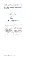
Test 1 - Check Gate Triggering
Gate triggering “on” can be demonstrated by using the 9V bat-
tery as a gate source and the megohmmeter as a high voltage
low current DC power source as indicated in figure 16. Use the
multimeter DC voltage range to determine the DC output volt-
age polarity of the megohmmeter if the megger is not marked.
Note: Gate and one cathode wire must be disconnected.
1. Connect megohmmeter positive lead to SCR anode ‘A’ and
connect meter negative to the SCR cathode ‘K.’
2. Connect 9V battery negative to the SCR cathode ‘K.’
Connect the 100-ohm resistor to battery positive.
3. Energize the megohmmeter and note reading.
4. Touch the open end of the 100-ohm resistor to the appropri-
ate SCR gate ‘TG’ or ‘LG.’ Megger reading should go to
short.
5. Open the resistor connection to the gate. The megger read-
ing should rise to the reading noted in step 3.
6. Repeat connections and test sequence on the other SCR in
the module to verify its gating.
This test is for gating only since the megger cannot provide
enough anode current to latch or hold the SCR “on.” The SCR
turns off when gate current is removed.
Figure 16
- Gate Triggering Test Diagram
30

