background image


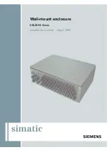
Wall-mount enclosure 6DL2804-0xxxx 
Hardware Installation Manual, 08/2009, A5E00378691N-02 

11


Description 

3

3.1


Overview 

The wall-mounted enclosures have the Ex e type of protection and are designed for use in 

hazardous areas ((Zones 1, 2, 21, 22; Mining: M2). The wall-mounted enclosure can be used 

for the installation of devices, components and fixtures with separate certificate. 
The wall-mounted enclosures comply with the requirements of the following standards:  


EN/IEC 60079-0 General requirements, 


EN/IEC 60079-7 Enhanced safety 


EN/ICE 61241-0 General requirements, 


EN/ICE 61241-1 Protection by means of enclosure. 

3.2


Application 


The wall-mounted enclosure is suitable for installation and operation of distributed I/O, for 

example ET 200iSP or ET 200 in hazardous areas of Zone 1 + 2 (gas), Zones 21 + 22 

(dust), and in mining (M2).  


The device has been tested and certified for use in these hazardous areas. 

Summary of Contents for Simatic 6DL2804-0 Series

Page 1: ...SIMATIC Distributed I O Wall mount enclosure 6DL2804 0xxxx simatic Installation manual Augst 2009 6DL2804 0xxxx Wall mount enclosure ...

Page 2: ......

Page 3: ...nting 4 Maintenance and servicing 5 Technical specifications 6 Connection diagram 7 Dimension drawing 8 ESD Guidelines 9 Service and support 10 SIMATIC Distributed I O Wall mount enclosure 6DL2804 0xxxx Hardware Installation Manual 08 2009 A5E00378691N 02 ...

Page 4: ...umentation for the specific task in particular its warning notices and safety instructions Qualified personnel are those who based on their training and experience are capable of identifying risks and avoiding potential hazards when working with these products systems Proper use of Siemens products Note the following WARNING Siemens products may only be used for the applications described in the c...

Page 5: ...ified personnel 9 2 4 Measures 10 3 Description 11 3 1 Overview 11 3 2 Application 11 3 3 Product features 12 3 4 Structure of the type designation 13 3 5 Details of the enclosure 14 4 Mounting 15 4 1 Transport and storage 15 4 2 Mounting the enclosure 16 4 3 Installing the enclosure outdoors 18 5 Maintenance and servicing 19 6 Technical specifications 21 7 Connection diagram 23 8 Dimension drawin...

Page 6: ...Table of contents Wall mount enclosure 6DL2804 0xxxx 6 Hardware Installation Manual 08 2009 A5E00378691N 02 ...

Page 7: ...It is intended for persons who install the device mechanically connect it electrically set parameters and commission it as well as for service and maintenance technicians 1 2 History The most important changes in the documentation compared with the previous edition are shown in the following table Edition Comment 01 2008 First edition 08 2009 Troubleshooting New functions see technical specificati...

Page 8: ...Introduction 1 2 History Wall mount enclosure 6DL2804 0xxxx 8 Hardware Installation Manual 08 2009 A5E00378691N 02 ...

Page 9: ...l Safety and Health Standard relating to the installation of electrical systems in hazardous areas DIN EN 60079 14 previously VDE 0165 T1 2 3 Qualified personnel Qualified personnel are people who are familiar with the installation mounting commissioning and operation of the product These people have the following qualifications They are authorized trained or instructed in operating and maintainin...

Page 10: ...he energy limited type of protection may be connected and disconnected while in operation Protection type non sparking nA zone 2 Devices with the non sparking type of protection may only be connected and disconnected when the power is disconnected WARNING Use in environments with aggressive and dangerous media The device can be operated both at high pressure and with aggressive and dangerous media...

Page 11: ...es with separate certificate The wall mounted enclosures comply with the requirements of the following standards EN IEC 60079 0 General requirements EN IEC 60079 7 Enhanced safety EN ICE 61241 0 General requirements EN ICE 61241 1 Protection by means of enclosure 3 2 Application The wall mounted enclosure is suitable for installation and operation of distributed I O for example ET 200iSP or ET 200...

Page 12: ...ices such as Distributed I O systems ET 200iSP for use in Zones 1 and 2 Zones 21 and 22 and M2 mining ET 200S for use in Zone 2 and Zone 22 ET 200M for use in Zone 2 and Zone 22 Modular electro pneumatic automation system AirLine Ex type 8650 from the firm of Bürkert Buffer stages and safety barriers Relays buffer elements and circuit breakers Separate terminals for intrinsically safe and non intr...

Page 13: ...ignation 0 3HUPLVVLEOH RSHUDWLQJ WHPSHUDWXUH UDQJH r RU KLJKHU SODVWLF EODFN 1 SHUPLVVLEOH RSHUDWLQJ WHPSHUDWXUH UDQJH r RU KLJKHU PHWDO 2 SHUPLVVLEOH RSHUDWLQJ WHPSHUDWXUH UDQJH r RU KLJKHU SODVWLF EOXH 6SHUPLVVLEOH RSHUDWLQJ WHPSHUDWXUH UDQJH r RU KLJKHU PHWDO IRU PLQLQJ ZLWK URZ IRU PLQLQJ ZLWK URZV IRU PLQLQJ ZLWK URZV 0 ZLWK URZV 0 ZLWK URZV 0 ZLWK URZV 0 6L H PP 6L H PP RQH JDV RQH GXVW 0 0L...

Page 14: ... be fitted The manufacturer s instructions regarding the tightening torque must be observed see description of manufacturer in enclosure Use the torque of the clamping screw when connecting the terminal of the cable For additional information and technical specifications refer the respective manufacturer documentation in particular Technical specifications regarding clamping ranges for cable Notes...

Page 15: ...distributed I O device in hazardous areas according to the specifications of the EC type examination certificate according to ATEX and these operating instructions or the examination certificate valid in your country Assembly installation commissioning and maintenance may only be performed by qualified personnel The devices and installed components must only be used for their intended purpose 4 1 ...

Page 16: ...lled horizontally this may lead to a reduction in the degree of protection Furthermore the operating ambient temperature is 30 C lower with vertical installation than with horizontal installation The temperature information on the type plate always applies to horizontal installation Therefore always install the device horizontal in such a way that the cable entries face downward NOTICE Remember th...

Page 17: ...the installed cables and lines are securely installed and check that there is sufficient strain relief It is not permitted to use the cable entry as strain relief 4 Route the cables and lines from below through the glands designated for these and tighten the clamping screw of the gland to the torque specified in the manufacturer s instructions 5 Install and connect the power supply cable the bus c...

Page 18: ...rotective measures depending on the environment of the installation location Avoid subjecting the enclosure permanently to water for example snow Remember that direct sunlight can cause excessive temperatures in the interior of the enclosure In locations where this can occur provide additional protection with some form of roofing Remember that opening the enclosure at ambient temperatures below 0 ...

Page 19: ...ge Adhesion of the gasket to the enclosure cover If there is damage to the enclosure there is a risk that the degree of protection is no longer valid In some cases this might necessitate replacement of the enclosure If there is damage to cable and wiring entries only replacement with original parts is permitted Check regularly once a year that the cable and line entries are securely in place and p...

Page 20: ...Maintenance and servicing Wall mount enclosure 6DL2804 0xxxx 20 Hardware Installation Manual 08 2009 A5E00378691N 02 ...

Page 21: ...potential bonding rail 3 x 10 mm Cu Bonding terminals 0 75 35mm Ex e for equipotential bonding wire 4mm for shield connection other terminals up to max 240mm depending on the type of terminal used Ground conductor M6 screw at least 16mm Rated voltage 1 Rated current 1 These values depend on the installed components Operating temperature range 2 20 C to 75 C or 40 C to 75 C 3 Permissible humidity m...

Page 22: ...Technical specifications Wall mount enclosure 6DL2804 0xxxx 22 Hardware Installation Manual 08 2009 A5E00378691N 02 ...

Page 23: ...rom the equipotential bonding rail to the enclosure IM EM terminal module with IM componentry IM interface module EM electronic module Cable for signal lines shield on equipotential bonding rail EM EM terminal module EM electronic module PROFIBUS cable to IM Mounting plate Bonding cable Mounting rail Power supply line to power supply Equipotential bonding rail with terminals M6 grounding connectio...

Page 24: ...Connection diagram Wall mount enclosure 6DL2804 0xxxx 24 Hardware Installation Manual 08 2009 A5E00378691N 02 ...

Page 25: ... componentry IM interface module EM electronic module Cable entry for signal lines M16 4 to 9 mm or M20 6 to 13 mm Terminal module EM EM with I O componentry I O Input Output Cable and wiring entry for PROFIBUS M20 Termination module Screw gland for pressure climate compensation Mounting rail Cable and wiring entry for power supply M32 13 to 21 mm Figure 8 1 Dimension drawing wall mounted enclosur...

Page 26: ...Dimension drawing Wall mount enclosure 6DL2804 0xxxx 26 Hardware Installation Manual 08 2009 A5E00378691N 02 ...

Page 27: ...es are commonly referred to as ESD devices This is also the international abbreviation for such devices ESD modules are identified by the following symbol CAUTION ESD devices can be destroyed by voltages well below the threshold of human perception These static voltages develop when you touch a component or electrical connection of a device without having discharged the static charges present on y...

Page 28: ...ODWLYH KXPLGLW LQ N9 Figure 9 1 Electrostatic voltages on an operator Basic protective measures against electrostatic discharge Ensure good equipotential bonding When handling electrostatic sensitive devices ensure that your body the workplace and packaging are grounded This prevents electrostatic charge Avoid direct contact As a general rule only touch electrostatic sensitive devices when this is...

Page 29: ... Catalog online ordering system http www siemens com automation mall Training All the training options are listed at http www siemens com sitrain Find a contact at Phone 49 911 895 3200 Technical support Tel 49 180 5050 222 Fax 49 180 5050 223 http www siemens com automation service You will find support request web form at http www siemens de automation support request If you contact customer sup...

Page 30: ...Service and support Wall mount enclosure 6DL2804 0xxxx 30 Hardware Installation Manual 08 2009 A5E00378691N 02 ...

Page 31: ...2 Relay 12 Safety barriers 12 Temperature sensors 12 Terminals 12 Double bit key 17 Drilling template for securing the device 16 E EC type examination certificate 15 Environmental conditions 18 ESD guidelines 27 G Guidelines ESD guidelines 27 H History 7 I Increased safety 10 Intrinsic safety 10 M Maintenance Cycles 19 Maintenance technicians 7 Media Aggressive 10 Dangerous 10 Modules Electrostati...

Page 32: ... support 29 Test certification 9 The Ordinance on Industrial Safety and Health 9 Training 29 Transport 15 Type of protection Energy limited nL zone 2 10 Increased safety 10 Intrinsic safety 10 Non sparking nA zone 2 10 Pressure resistant encapsulation 10 W Wall mounting 16 Wall mounted enclosure 12 Wall mounted enclosure 11 Z Zone 2 10 ...

Page 33: ......

Page 34: ...www automation siemens com simatic Siemens AG Industry Sector Industrial Automation and Drive Technologies P O Box 4848 90327 NUERMBERG Germany Subject to change ID A5E00378691N 02 Siemens AG 2009 www siemens com automation ...

Reviews: