


Wall-mount enclosure 6DL2804-0xxxx
Hardware Installation Manual, 08/2009, A5E00378691N-02
25
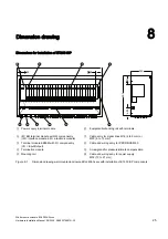
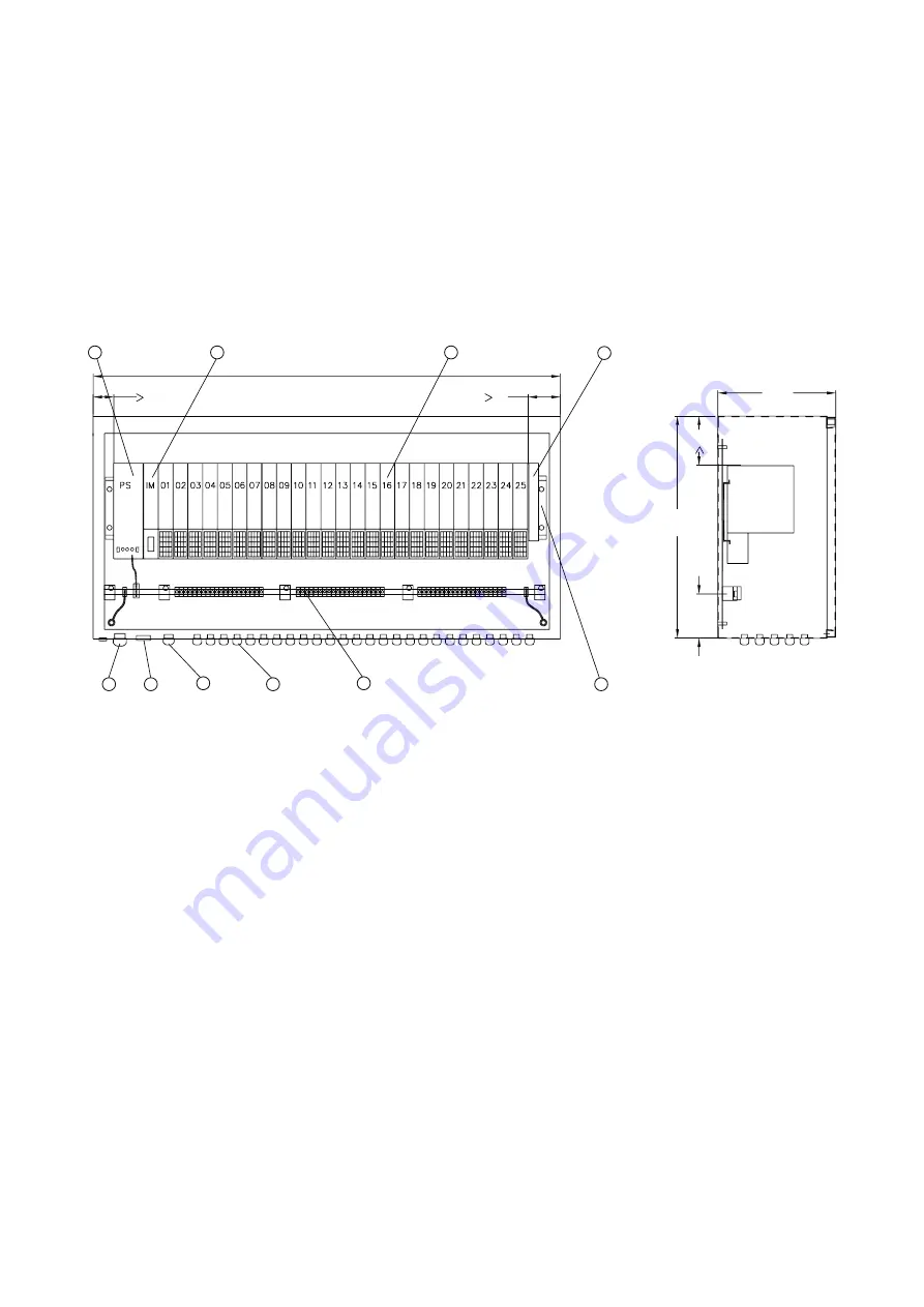
Dimension drawing
8
Dimensions for installation of ET200 iSP
F
D
① Power supply terminal module
⑥ Equipotential bonding rail with terminals
② IM / EM terminal module with IM componentry
(IM = interface module, EM = electronic module)
⑦ Cable entry for signal lines M16 (4 to 9 mm) or
M20 (6 to 13 mm)
③ Terminal module EM/EM with I/O componentry
(I/O = Input/Output)
⑧ Cable and wiring entry for PROFIBUS M20
④ Termination module
⑨ Screw gland for pressure/climate compensation
⑤ Mounting rail
⑩ Cable and wiring entry for power supply
M32 (13 to 21 mm)
Figure 8-1
Dimension drawing wall-mounted enclosure 6DL2804-0xxxx with installation of ET200 iSP components