Glossary-8
C7-621 / C7-621 AS-i Control Systems
C79000-G7076-C621-01
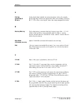
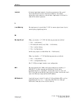
The signal states of the digital inputs and outputs are stored in the C7 CPU in
a process image. There are two process images: the process image input table
(PII) and the process image output table (PIQ).
The process image input table is read by the input modules before execution
of the user program.
The process image output table is transferred to the output modules by the
operating system at the end of the user program.
Programmable controllers (PLCs) are electronic controllers whose function is
stored as a program in the CPU. The design and wiring of these devices
therefore does not depend on the controller function. The programmable
controller has the structure of a computer; it consists of a CPU with memory,
inputs and outputs and an internal bus system. The I/O and the programming
language are designed specifically for the requirements of control
engineering.
Programming devices are essentially personal computers that are compact
and portable and suitable for use in industry. They are characterized by being
equipped with special hardware and software for SIMATIC programmable
controllers.
R
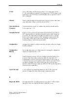
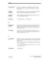
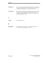
Random access memory is a read/write memory in which each memory cell
can be addressed individually and can be changed. RAM memories are used
as data memories and program memories.
–> Ground
Potential to which from which the voltages of the connected circuits are
referred.
S
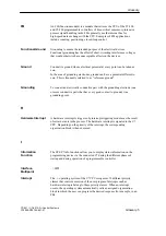
The scan cycle time is the time required by the –> C7 to execute the –> user
program once.
Signal modules (C7 I/Os) form the interface between the process and the C7.
There are digital input and output modules and analog input and output
modules.
Process Image
Programmable
Logic Controller
Programming
Device
RAM
Reference Ground
Reference
Potential
Scan Cycle Time
Signal Module
Glossary
Summary of Contents for simatic c7-621
Page 44: ...2 26 C7 621 C7 621 AS i Control Systems C79000 G7076 C621 01 Installing and Preparing the C7 ...
Page 64: ...3 20 C7 621 C7 621 AS i Control Systems C79000 G7076 C621 01 Configuring an MPI Network ...
Page 74: ...5 4 C7 621 C7 621 AS i Control Systems C79000 G7076 C621 01 Attaching a C7 621 AS i ...
Page 82: ...6 8 C7 621 C7 621 AS i Control Systems C79000 G7076 C621 01 C7 621 Digital I Os ...
Page 100: ...7 18 C7 621 C7 621 AS i Control Systems C79000 G7076 C621 01 C7 621 Analog I Os ...
Page 101: ...8 1 C7 621 C7 621 AS i Control Systems C79000 G7076 C621 01 Maintenance 8 ...
Page 110: ...A 8 C7 621 C7 621 AS i Control Systems C79000 G7076 C621 01 General Technical Specifications ...
Page 123: ...Glossary 1 C7 621 C7 621 AS i Control Systems C79000 G7076 C621 01 Glossary ...
Page 136: ...Index 4 C7 621 C7 621 AS i Control Systems C79000 G7076 C621 01 Index ...


