Glossary-9
C7-621 / C7-621 AS-i Control Systems
C79000-G7076-C621-01
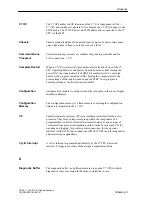
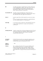
Programming software for creating user programs for SIMATIC 87
programmable controllers.
A STEP 7 tool is a tool of –> STEP 7 tailored to a specific task.
Substitute values are values that are output to the process or used in the user
program in place of a process value in the event of a fault occurring in signal
modules. The substitute values can be specified by the user (for example,
keep old value).
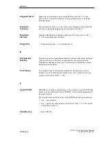
System diagnostics includes the detection, evaluation and signaling of faults
occurring within the programmable controller. Examples of such faults
include program errors or module failures. System faults can be displayed via
LEDs or using the S7 Information tool.
The system memory is integrated on the CPU and implemented in the form
of a RAM. The address areas (for example, timers, counters, memory bits)
and the data areas required internally by the operating system (for example,
buffers for communications) are stored in the system memory.
T
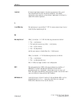
The time-delay interrupt belongs to one of the priority classes in program
execution on the C7 CPU. It is generated after expiry of a time started in the
user program. The associated organization block is then executed.
The time-of-day interrupt belongs to one of the priority classes in program
execution on the C7 CPU. It is generated dependent on a specific date (or
daily) and time (for example, 9:50 or hourly, or every minute). The
associated organization block is then executed.
³
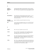
STEP 7 tool
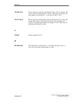
Sum of the currents of all output channels of a digital output module.
U
Without electrical connection to –> ground
STEP 7
STEP 7 Tool
Substitute Value
System
Diagnostics
System Memory
Time-Delay
Interrupt
Time-of-Day
Interrupt
Tool
Total Current
Ungrounded
Glossary
Summary of Contents for simatic c7-621
Page 44: ...2 26 C7 621 C7 621 AS i Control Systems C79000 G7076 C621 01 Installing and Preparing the C7 ...
Page 64: ...3 20 C7 621 C7 621 AS i Control Systems C79000 G7076 C621 01 Configuring an MPI Network ...
Page 74: ...5 4 C7 621 C7 621 AS i Control Systems C79000 G7076 C621 01 Attaching a C7 621 AS i ...
Page 82: ...6 8 C7 621 C7 621 AS i Control Systems C79000 G7076 C621 01 C7 621 Digital I Os ...
Page 100: ...7 18 C7 621 C7 621 AS i Control Systems C79000 G7076 C621 01 C7 621 Analog I Os ...
Page 101: ...8 1 C7 621 C7 621 AS i Control Systems C79000 G7076 C621 01 Maintenance 8 ...
Page 110: ...A 8 C7 621 C7 621 AS i Control Systems C79000 G7076 C621 01 General Technical Specifications ...
Page 123: ...Glossary 1 C7 621 C7 621 AS i Control Systems C79000 G7076 C621 01 Glossary ...
Page 136: ...Index 4 C7 621 C7 621 AS i Control Systems C79000 G7076 C621 01 Index ...

