2-18
C7-621 / C7-621 AS-i Control Systems
C79000-G7076-C621-01
2.9
I/O Expansion with the IM 621
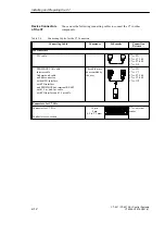
You can connect further S7-300 I/Os to the C7 via the P bus connector of the
C7-621 or C7-621 AS-i.
How you install the S7 modules, is described in the manual /71/.
Note
You can connect a maximum of four I/O modules to the C7.
The S7-300 system must have an IM 621 interface module.
Connect the additional I/Os as following:
1. Install the additional I/O modules as described for the rack in the
manual /70/.
2. Connect the C7-621 or C7-621 AS-i to the IM 621 interface module via
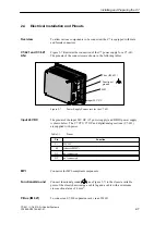
an IM 621 standard cable (for the connection to C7, see also Figure 2-9).
An IM 621 cable is supplied with the module and is connected to the IM
621 interface module.
The first time you start up the C7, it detects the connected additional
modules.
Addressing on the C7 is described in Volume 2 Chapter 4.
The C7 has an integrated P bus interface for I/O expansions with external
S7-300 standard I/Os.
Additional S7-300
Modules
Requirements
Connecting the
Additional I/Os
Addresses
P Bus Interface
Installing and Preparing the C7
Summary of Contents for simatic c7-621
Page 44: ...2 26 C7 621 C7 621 AS i Control Systems C79000 G7076 C621 01 Installing and Preparing the C7 ...
Page 64: ...3 20 C7 621 C7 621 AS i Control Systems C79000 G7076 C621 01 Configuring an MPI Network ...
Page 74: ...5 4 C7 621 C7 621 AS i Control Systems C79000 G7076 C621 01 Attaching a C7 621 AS i ...
Page 82: ...6 8 C7 621 C7 621 AS i Control Systems C79000 G7076 C621 01 C7 621 Digital I Os ...
Page 100: ...7 18 C7 621 C7 621 AS i Control Systems C79000 G7076 C621 01 C7 621 Analog I Os ...
Page 101: ...8 1 C7 621 C7 621 AS i Control Systems C79000 G7076 C621 01 Maintenance 8 ...
Page 110: ...A 8 C7 621 C7 621 AS i Control Systems C79000 G7076 C621 01 General Technical Specifications ...
Page 123: ...Glossary 1 C7 621 C7 621 AS i Control Systems C79000 G7076 C621 01 Glossary ...
Page 136: ...Index 4 C7 621 C7 621 AS i Control Systems C79000 G7076 C621 01 Index ...

