3-15
C7-621 / C7-621 AS-i Control Systems
C79000-G7076-C621-01
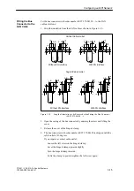
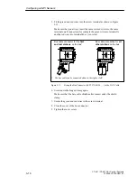
Fit the bus connector with order number 6ES7 972-0B.20 ... to the LAN
cable as follows:
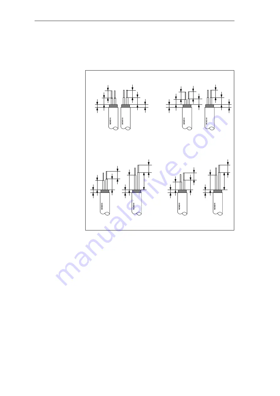
1. Strip the insulation from the LAN cable as shown in Figure 3-10.
5.5
11
13
2
A B
5.5
6
7,3
2
A B
5.5
5.5
4
4,3
2
A B
5.5
5.3
2
A B
With PG interface
5.5
5
2
A B
5.5
5.3
2
A B
5.5
7
8
2
A B
With PG interface
5.5
11
13
2
A B
Vertical Cable Outlet
Without PG interface
Angled Cable Outlet
Without PG interface
Figure 3-10
Length of Insulation to be Removed when Fitting the Bus Connector
(6ES7 972-0B.20 ...)
2. Open the casing of the bus connector by undoing the screw and lifting the
cover.
3. Release the cover of the hinged clamp.
4. The bus connector with order number 6ES7 972-0B.20 is shipped with the
cable outlet at 30 degrees.
If you require a vertical cable outlet,
–
Loosen the left screw on the hinged clamp,
–
Lever the hinged clamp upwards slightly
–
Turn the hinged clamp inwards.
–
To fix the clamp in position tighten the left screw again.
Fitting the Bus
Connector to the
LAN Cable
Configuring an MPI Network
Summary of Contents for simatic c7-621
Page 44: ...2 26 C7 621 C7 621 AS i Control Systems C79000 G7076 C621 01 Installing and Preparing the C7 ...
Page 64: ...3 20 C7 621 C7 621 AS i Control Systems C79000 G7076 C621 01 Configuring an MPI Network ...
Page 74: ...5 4 C7 621 C7 621 AS i Control Systems C79000 G7076 C621 01 Attaching a C7 621 AS i ...
Page 82: ...6 8 C7 621 C7 621 AS i Control Systems C79000 G7076 C621 01 C7 621 Digital I Os ...
Page 100: ...7 18 C7 621 C7 621 AS i Control Systems C79000 G7076 C621 01 C7 621 Analog I Os ...
Page 101: ...8 1 C7 621 C7 621 AS i Control Systems C79000 G7076 C621 01 Maintenance 8 ...
Page 110: ...A 8 C7 621 C7 621 AS i Control Systems C79000 G7076 C621 01 General Technical Specifications ...
Page 123: ...Glossary 1 C7 621 C7 621 AS i Control Systems C79000 G7076 C621 01 Glossary ...
Page 136: ...Index 4 C7 621 C7 621 AS i Control Systems C79000 G7076 C621 01 Index ...

