4-5
C7-621 / C7-621 AS-i Control Systems
C79000-G7076-C621-01
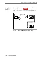
For installation or maintenance purposes, attach the programming device/PC
to a node of the MPI network using a tap line. The bus connector of this node
must have a PG interface (see also Section 3.5).
Figure 4-3 shows two networked C7s to which a programming device/PC is
connected.
PROFIBUS LAN cable
PG cable = tap
line
C7
PG/PC
C7
Figure 4-3
Attaching a Programming Device/PC to an MPI Network
Programming
Device/PC for
Installation or
Maintenance
Connecting a Programming Device / PC to a C7
Summary of Contents for simatic c7-621
Page 44: ...2 26 C7 621 C7 621 AS i Control Systems C79000 G7076 C621 01 Installing and Preparing the C7 ...
Page 64: ...3 20 C7 621 C7 621 AS i Control Systems C79000 G7076 C621 01 Configuring an MPI Network ...
Page 74: ...5 4 C7 621 C7 621 AS i Control Systems C79000 G7076 C621 01 Attaching a C7 621 AS i ...
Page 82: ...6 8 C7 621 C7 621 AS i Control Systems C79000 G7076 C621 01 C7 621 Digital I Os ...
Page 100: ...7 18 C7 621 C7 621 AS i Control Systems C79000 G7076 C621 01 C7 621 Analog I Os ...
Page 101: ...8 1 C7 621 C7 621 AS i Control Systems C79000 G7076 C621 01 Maintenance 8 ...
Page 110: ...A 8 C7 621 C7 621 AS i Control Systems C79000 G7076 C621 01 General Technical Specifications ...
Page 123: ...Glossary 1 C7 621 C7 621 AS i Control Systems C79000 G7076 C621 01 Glossary ...
Page 136: ...Index 4 C7 621 C7 621 AS i Control Systems C79000 G7076 C621 01 Index ...

