5-2
C7-621 / C7-621 AS-i Control Systems
C79000-G7076-C621-01
5.1
AS-i Attachments
The C7-621 AS-i has connectors for two AS-i cables that are connected
internally in the C7. The maximum load on the contacts is 4 A.
You can connect the following to the AS-i connectors:
S
Actuators, sensors
S
AS-i power supply unit
The AS-i CP is not supplied with power via the 24V DC input. The AS-i CP
must be supplied with power via terminals AS-i+ and AS-i-.
Connect the power supply unit either directly to the C7-621 AS-i or supply
power to the AS-i CP in the C7-621 AS-i by connecting the AS-i power
supply in the network with the actuators or sensors.
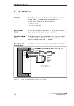
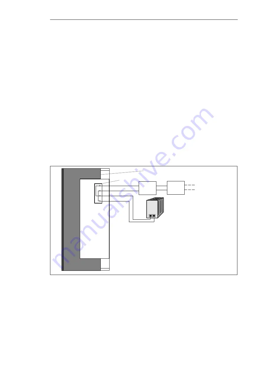
Figure 5-1 shows the connections and block diagram of the AS-i terminals.
AS-i terminals
Block diagram of
the AS-i terminals
View from the right side of the C7-621 AS-i
Sensor 1
AS-i
power
supply
unit
Sensor 2
AS-i-
AS-i+
AS-i-
AS-i+
(blue)
(brown)
Figure 5-1
Connections and Block Diagram of the AS-i Terminals
Properties
AS-i CP Power
Supply
AS-i Power Supply
Unit
Connections and
Block Diagram
Attaching a C7-621 AS-i
Summary of Contents for simatic c7-621
Page 44: ...2 26 C7 621 C7 621 AS i Control Systems C79000 G7076 C621 01 Installing and Preparing the C7 ...
Page 64: ...3 20 C7 621 C7 621 AS i Control Systems C79000 G7076 C621 01 Configuring an MPI Network ...
Page 74: ...5 4 C7 621 C7 621 AS i Control Systems C79000 G7076 C621 01 Attaching a C7 621 AS i ...
Page 82: ...6 8 C7 621 C7 621 AS i Control Systems C79000 G7076 C621 01 C7 621 Digital I Os ...
Page 100: ...7 18 C7 621 C7 621 AS i Control Systems C79000 G7076 C621 01 C7 621 Analog I Os ...
Page 101: ...8 1 C7 621 C7 621 AS i Control Systems C79000 G7076 C621 01 Maintenance 8 ...
Page 110: ...A 8 C7 621 C7 621 AS i Control Systems C79000 G7076 C621 01 General Technical Specifications ...
Page 123: ...Glossary 1 C7 621 C7 621 AS i Control Systems C79000 G7076 C621 01 Glossary ...
Page 136: ...Index 4 C7 621 C7 621 AS i Control Systems C79000 G7076 C621 01 Index ...


