2-15
C7-621 / C7-621 AS-i Control Systems
C79000-G7076-C621-01
2.6
Connecting Up Cables
This chapter describes how to connect the shield of shielded signal cables
with ground. The shield is connected directly to the ground terminal of the
C7 via a grounding bar.
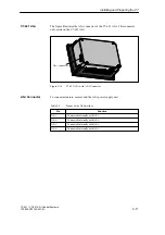
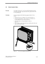
Fit the grounding bar and the shield clips supplied with the C7-621 as
follows:
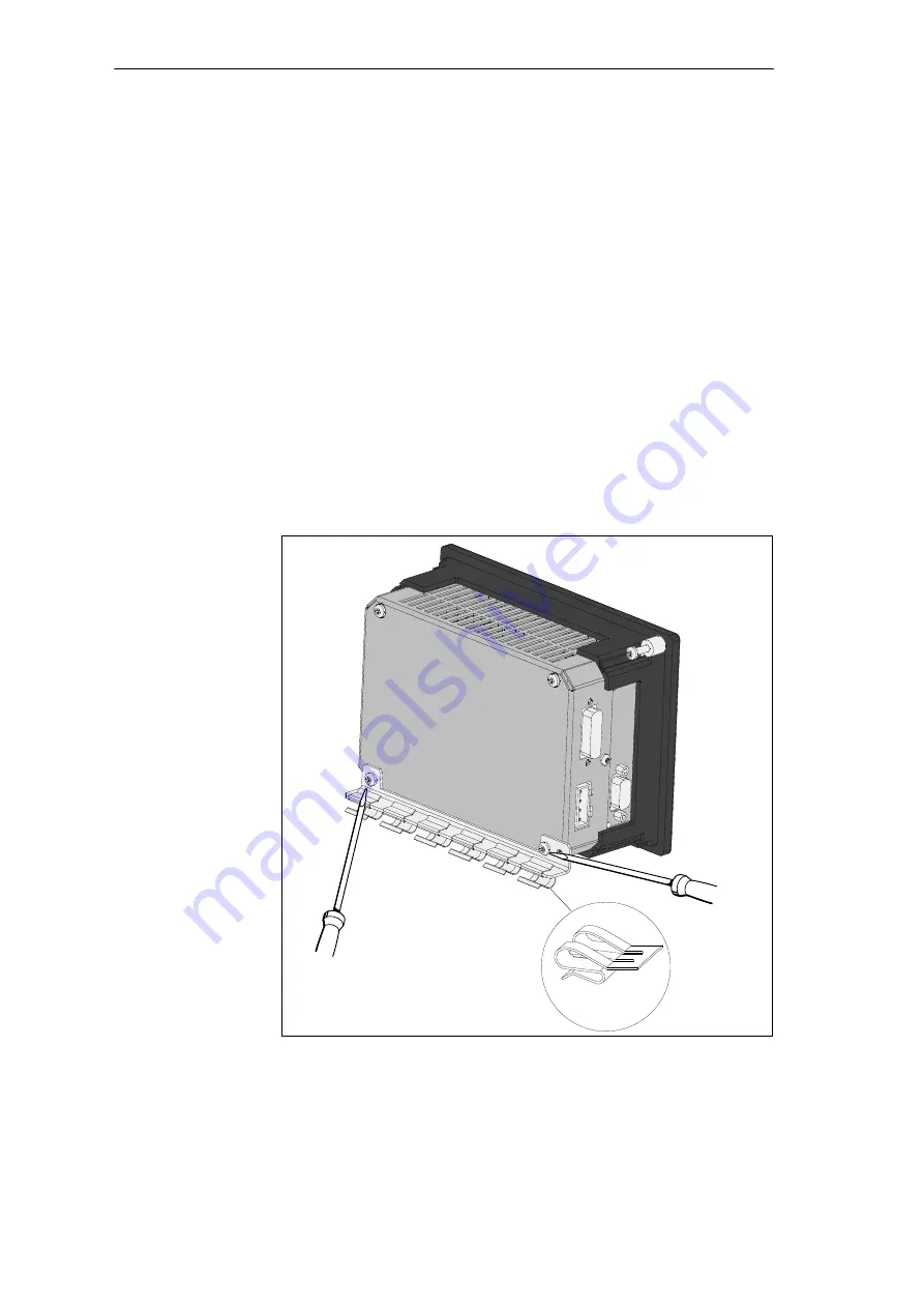
1. Remove the two screws from the C7-621 as shown in Figure 2-11.
2. Position the grounding bar as shown in Figure 2-11 and fasten it in
position with the two screws previously removed.
3. Fit the shield clips on to the grounding bar as shown in
Figure 2-11.
4. Press the stripped cable into the shield clips so that the shield of the cable
makes the best possible contact.
Shield clip
Figure 2-11
C7-621 with Grounding Bar and Shield Clips
Overview
Procedure
Installing and Preparing the C7
Summary of Contents for simatic c7-621
Page 44: ...2 26 C7 621 C7 621 AS i Control Systems C79000 G7076 C621 01 Installing and Preparing the C7 ...
Page 64: ...3 20 C7 621 C7 621 AS i Control Systems C79000 G7076 C621 01 Configuring an MPI Network ...
Page 74: ...5 4 C7 621 C7 621 AS i Control Systems C79000 G7076 C621 01 Attaching a C7 621 AS i ...
Page 82: ...6 8 C7 621 C7 621 AS i Control Systems C79000 G7076 C621 01 C7 621 Digital I Os ...
Page 100: ...7 18 C7 621 C7 621 AS i Control Systems C79000 G7076 C621 01 C7 621 Analog I Os ...
Page 101: ...8 1 C7 621 C7 621 AS i Control Systems C79000 G7076 C621 01 Maintenance 8 ...
Page 110: ...A 8 C7 621 C7 621 AS i Control Systems C79000 G7076 C621 01 General Technical Specifications ...
Page 123: ...Glossary 1 C7 621 C7 621 AS i Control Systems C79000 G7076 C621 01 Glossary ...
Page 136: ...Index 4 C7 621 C7 621 AS i Control Systems C79000 G7076 C621 01 Index ...

