background image

2-17

C7-621 / C7-621 AS-i Control Systems
C79000-G7076-C621-01

2.8

Contrast

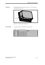
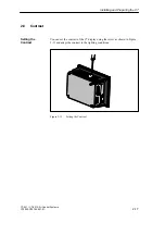
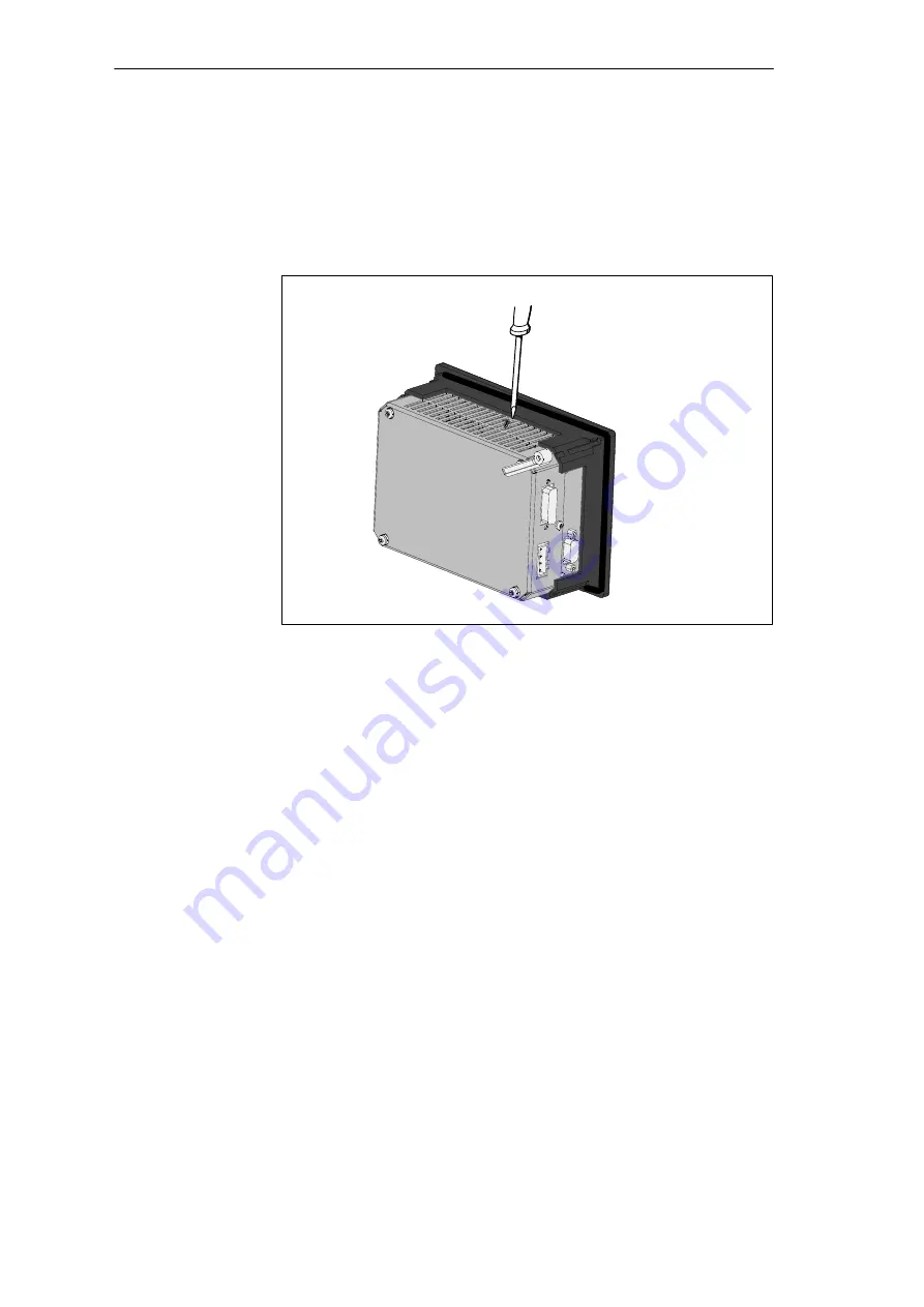
You can set the contrast of the C7 display using the screw as shown in Figure
2-13 and adapt the contrast to the lighting conditions.

Figure 2-13

Setting the Contrast

Setting the
Contrast

Installing and Preparing the C7

Summary of Contents for simatic c7-621

Page 1: ... C7 4 AS i Attaching a C7 621 AS i 5 I Os C7 621 Digital I Os 6 C7 621 Analog I Os 7 Maintenance 8 Appendix General Technical Specifica tions A Guidelines for Handling ESD Devices B Safety of Electronic Controllers C SIMATIC C7 and S7 Refer ences D Glossary Index C79000 G7076 C621 01 C7 621 C7 621 AS i Control Systems Volume 1 Hardware and Installation Manual SIMATIC ...

Page 2: ...ribedinthecatalogorthetechnical description and only in connection with devices or components from other manufacturers which have been approved or recommended by Siemens Thisproductcanonlyfunctioncorrectlyandsafelyifitistransported stored setup andinstalledcorrectly and operated and maintained as recommended SIMATICR and SMATIC NETR are registered trademarks of SIEMENS AG Third parties using for t...

Page 3: ...groups of readers S Volume 1 Users installing the C7 mechanically and electrically on site and preparing the C7 so that it is ready for operation S Volume 2 Users creating control programs and operator interface configurations and downloading them to the C7 This manual describes the hardware and software of the C7 621 and C7 621 AS i It consists of two volumes Volume 1 of the manual deals with the...

Page 4: ...y by called C7 in the manual If the device is simply called C7 in the manual the information applies to both versions of the control system Where differences occur the full name of the unit will be used This manual is valid for the following C7s C7 Order Number Versions and Higher C7 621 6ES7621 1AD00 0AE3 01 C7 621 AS i 6ES7621 6BD00 0AE3 01 This manual can be obtained under the order number 6ES7...

Page 5: ... 400 System and Standard Functions STEP7 User Manual Program Design ProTool Lite Module Specifications ProTool To familiarize yourself with the AS i system we recommend the following procedure S You should certainly read the AS i brochure Actuator Sensor Interface Order number E20001 P285 A497 V2 X 7600 This brochure can be ordered from all Siemens offices C7 621 AS i Brochure Preface ...

Page 6: ...00 400 Programming or Manual LAD for S7 300 400 Programming Reference manuals for programming with STL or LAD S Basics of working with STL LAD for example structure of STL LAD numerical formats syntax S Description of all instructions in STEP 7 with program examples S Description of the various ways of addressing in STEP 7 with examples S Description of all integrated functions on the CPUs S Descr...

Page 7: ...les S Using block call instructions S Overview of using STEP 7 tools for developing projects with an extensive example S Using test and diagnostic functions of the CPUs in user programs for example error OBs status word Manual S7 300 Programmable Controller Hardware and Installation This manual describes the hardware of the S7 300 S Configuring the S7 300 S Installing the S7 300 S Wiring and prepa...

Page 8: ...as follows S At the start of both volumes of the manual you will find a complete table of contents S In the left margin of the chapters there is a subtitle indicating the content of the section S After the appendix there is a glossary listing important terminology used in the manual S At the end of the manual there is a detailed subject index The C7 control system complies with the standards descr...

Page 9: ...1 Status and Error LEDs on the C7 2 23 2 12 Clocks on the C7 2 24 3 Configuring an MPI Network 3 1 3 1 Communication via the MPI Interface 3 2 3 2 Rules for Configuring an MPI Network 3 4 3 3 Cable Lengths 3 8 3 4 Network Components 3 10 3 5 Bus Connectors 3 12 3 5 1 PROFIBUS Bus Connector 3 13 3 5 2 Bus Connector 6ES7 972 0B 20 0XA0 3 14 3 5 3 Bus Connector 6ES7 972 0B 10 0XA0 3 17 3 5 4 Connecti...

Page 10: ...11 7 4 Analog Output 7 15 8 Maintenance 8 1 A General Technical Specifications A 1 A 1 Technical Specifications A 2 A 2 Notes on the CE Approval A 5 A 3 Notes for Manufacturers of Machines A 7 B Guidelines for Handling Electrostatically Sensitive Devices ESD B 1 B 1 What is ESD B 2 B 2 Electrostatic Charging of Objects and Persons B 3 B 3 General Protective Measures Against Electrostatic Discharge...

Page 11: ...ion of the two devices This chapter also explains the additional components that you can connect to a C7 To install and start up the C7 you require the following accessories S Programming device or PC with an MPI interface and PG cable S The following software must be loaded on the programming device or PC STEP 7 Tools ProTool or ProTool Lite In This Chapter Accessories for Installing and Starting...

Page 12: ...e Figure 1 1 C7 621 You can do the following with the C7 621 S Run user programs that were written in STL LAD or FBD and downloaded to the C7 CPU S Process digital and analog signals using the I Os integrated on the C7 S Download and use operator interface applications that you created with the ProTool or ProTool Lite configuration tool S Using these configurations you can monitor and intervene in...

Page 13: ...ion for the IM 621 module This model does not have digital inputs outputs and analog inputs outputs Figure 1 2 C7 621 AS i You can do the following with the C7 621 AS i control system S Run user programs that were written in STL LAD or FBD and downloaded to the C7 CPU S Connect actuators and sensors via the AS interface to the C7 621 AS i S Download and use operator interface applications that you...

Page 14: ... G7076 C621 01 The C7 has two independent units that communicate with each other via an internal MPI interface S C7 CPU with C7 AS i CP S C7 OP When necessary these units are dealt with separately in the manuals C7 621 AS i Units Product Overview ...

Page 15: ...l input modules digital output modules analog input modules analog output modules analog input output modules adapt various process signal levels to the C7 CPU Can be connected to the C7 via an IM 621 S7 300 CPU communicates via the MPI interface with C7 and with other nodes on an MPI network S7 400 CPU communicates via the MPI interface with C7 and other nodes on an MPI network OP Operator Panel ...

Page 16: ...ce PG or PC with the STEP 7 software package and ProTool or Pro Tool Lite configures assigns parameters programs and tests the C7 RS 485 repeater amplifies the signals in an MPI or PROFIBUS DP network and connects segments of an MPI or PROFIBUS DP network Sensors and actuators AS i slaves Refer to the various catalogs applies only to the C7 621 AS i Product Overview ...

Page 17: ...control systems and OPs S An AS interface AS i for connecting sensors and actuators version C7 621 AS i see Figure 1 4 C7 621 C7 I Os P bus MPI interface C7 CPU C7 OP CPU memory C7 CPU OP memory C7 OP STEP 7 ProTool Lite or ProTool Figure 1 3 Components of the C7 621 The individual components integrated in the SIMATIC C7 correspond to the components that can also be used in the modular configurati...

Page 18: ...ller and OP families the individual components operate independently of each other and each of the processors has its own memory C7 CPU is programmed with STEP 7 and the C7 OP is configured with ProTool Lite C7 621 AS i C7 AS i MPI interface C7 CPU C7 OP CPU memory C7 CPU OP memory C7 OP STEP 7 ProTool Lite or ProTool P Bus Figure 1 4 Components of the C7 621 AS i Product Overview ...

Page 19: ...ling a C7 2 3 2 3 Location of the C7 2 6 2 4 Electrical Installation and Pinouts 2 7 2 5 Guidelines for Trouble Free Installation 2 13 2 6 Connecting Up Cables 2 15 2 7 Connector Key Inserts 2 16 2 8 Contrast 2 17 2 9 I O Expansion with the IM 621 2 18 2 10 Memory Reset on the C7 2 20 2 11 Status and Error LEDs on the C7 2 23 2 12 Clocks on the C7 2 24 Chapter Overview 2 ...

Page 20: ...nectors for AS i and C7 power supply with key inserts S Product information The following components can be ordered as accessories for the C7 S Manual C7 621 C7 621 AS i Control Systems consisting of two volumes in the following languages German 6ES7 621 1AD00 8AA0 English 6ES7 621 1AD00 8BA0 French 6ES7 621 1AD00 8CA0 Italian 6ES7 621 1AD00 8DA0 Spanish 6ES7 621 1AD00 8EA0 S Service package seal ...

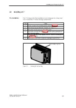
Page 21: ... 2 2 Insert the sealing ring behind the front panel see Figure 2 1 3 Insert the C7 into the cutout in the switching panel 4 Insert the 4 securing posts see Figure 2 3 into the guides pushing them until the spring engages 5 Screw the 4 securing screws supplied with the C7 into the 4 securing posts see Figure 2 4 6 Tighten the 4 screws with a screwdriver tightening torque 0 6 Nm Insert sealing ring ...

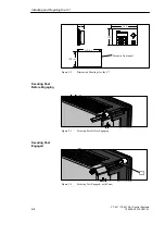
Page 22: ...1 120 168 68 159 0 5 110 0 5 Cutout in front panel Figure 2 2 Dimension Drawings for the C7 Figure 2 3 Securing Post Before Engaging Figure 2 4 Securing Post Engaged with Screw Securing Post Before Engaging Securing Post Engaged Installing and Preparing the C7 ...

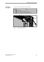
Page 23: ...curing post follow the steps outlined below Step Action 1 Loosen the screw 2 Lever the securing post upwards in Figure 2 5 3 Lever the securing post out of the guide in Figure 2 5 Figure 2 5 Removing the Securing Post Releasing the Securing Post Installing and Preparing the C7 ...

Page 24: ... the sealing ring makes a tight seal all round S There must be a clearance of at least 50 mm above and below and 70 mm at the sides of the C7 as shown in Figure 2 6 S Make sure that the sealing ring on the front panel sits correctly S Choose a location for the C7 away from direct sunlight 50 50 70 70 Figure 2 6 Minimum Clearances when Installing the C7 Points to Note When Installing the C7 Install...

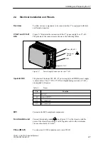
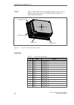
Page 25: ... C7 621 The pinout of the input 24V DC C7 power supply and DI DO power supply is shown below The C7 CPU C7 OP and digital analog sections C7 621 are supplied with power Table 2 1 Pinout Pin Function L DC 24V M chassis M24V NC not connected NC not connected Connector for MPI compliant components Connect functional ground see Figure 2 7 to the closest available point of the closet chassis using a ca...

Page 26: ... View of a C7 621 with External I O Ports Table 2 2 Pinout of the Digital Inputs Pin Signal Function 0 0 I124 0 Digital input 0 0 1 I124 1 Digital input 1 0 2 I124 2 Digital input 2 0 3 I124 3 Digital input 3 0 4 I124 4 Digital input 4 0 5 I124 5 Digital input 5 0 6 I124 6 Digital input 6 0 7 I124 7 Digital input 7 1 0 I125 0 Digital input 8 1 1 I125 1 Digital input 9 1 2 I125 2 Digital input 10 1...

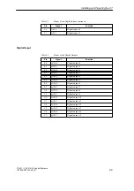
Page 27: ...0 0 1 Q124 1 Digital output 1 0 2 Q124 2 Digital output 2 0 3 Q124 3 Digital output 3 0 4 Q124 4 Digital output 4 0 5 Q124 5 Digital output 5 0 6 Q124 6 Digital output 6 0 7 Q124 7 Digital output 7 1 0 Q125 0 Digital output 8 1 1 Q125 1 Digital output 9 1 2 Q125 2 Digital output 10 1 3 Q125 3 Digital output 11 1 4 Q125 4 Digital output 12 1 5 Q125 5 Digital output 13 1 6 Q125 6 Digital output 14 1...

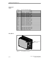
Page 28: ...alog input 2 reference potential AI3 U Analog input 3 signal input for voltage AI3 I Analog input 3 signal input for current AI3 M Analog input 3 reference potential AI4 U Analog input 4 signal input for voltage AI4 I Analog input 4 signal input for current AI4 M Analog input 4 reference potential AO U Analog output signal output für voltage AO I Analog output signal output für current AO M Analog...

Page 29: ...S i connector Figure 2 10 C7 621 AS i with AS i Connector To connect actuators sensors and the AS i power supply unit Table 2 5 Pinout of the AS Interface Pin Function AS i Connected internally with AS i AS i Connected internally with AS i AS i Connected internally with AS i AS i Connected internally with AS i C7 621 AS i AS i Connector Installing and Preparing the C7 ...

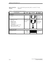
Page 30: ...7 S7 300 C7 S7 400 C7 OP PROFIBUS LAN cable Interior cable Underground cable and bus connector without PG interface with PG interface and PROFIBUS bus terminal RS 485 with 1 5 m and 3 m cable with PG interface and 1 5 m cable The cable must be assembled by the user C7 PG C7 C7 C7 S7 300 C7 S7 400 C7 OP Connectors for C7 I Os Connector for C7 I Os Conductor cross section 16 pin 4 pin 0 2 to 2 5 mm2...

Page 31: ...to power lines Use a separate cable duct for signal lines with a minimum clearance of 50 cm to power lines Install devices that could introduce interference signals from the outside at the bottom of the wiring closet The grounding rail should be located directly at the point of entry to the closet so that cables that could be carrying interference signals can be connected directly to ground The sh...

Page 32: ...high electrostatic voltages for example textile machinery the grounding cables of the machine parts producing high voltage interference signals should be connected to a separate ground surface grounding with building construction reinforcement from the grounding point of the wiring closet The manual 70 contains installation guidelines and deals with measures for protecting from interference Measur...

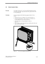
Page 33: ... with the C7 621 as follows 1 Remove the two screws from the C7 621 as shown in Figure 2 11 2 Position the grounding bar as shown in Figure 2 11 and fasten it in position with the two screws previously removed 3 Fit the shield clips on to the grounding bar as shown in Figure 2 11 4 Press the stripped cable into the shield clips so that the shield of the cable makes the best possible contact Shield...

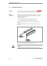
Page 34: ...ng receptacle without having to sacrifice a pin Follow the steps below 1 Insert solid keys into the grooves on the connector 2 Insert the profile keys into the cutouts on the housing Where solid and profile keys face each other the connector cannot be inserted If the solid and profile keys do not face each other the connector can be inserted 1 2 3 4 5 6 7 8 9 10 Figure 2 12 Preventing Insertion of...

Page 35: ...0 G7076 C621 01 2 8 Contrast You can set the contrast of the C7 display using the screw as shown in Figure 2 13 and adapt the contrast to the lighting conditions Figure 2 13 Setting the Contrast Setting the Contrast Installing and Preparing the C7 ...

Page 36: ... modules as described for the rack in the manual 70 2 Connect the C7 621 or C7 621 AS i to the IM 621 interface module via an IM 621 standard cable for the connection to C7 see also Figure 2 9 An IM 621 cable is supplied with the module and is connected to the IM 621 interface module The first time you start up the C7 it detects the connected additional modules Addressing on the C7 is described in...

Page 37: ...1 01 124 0 125 7 4 5 6 7 Slot number Modules IM 621 Digital address 128 135 Analog address Figure 2 14 Maximum Configuration with a C7 621 5 6 7 8 Slot number Modules IM 621 Figure 2 15 Maximum Configuration for a C7 621 AS i Installing and Preparing the C7 ...

Page 38: ...nfiguration is deleted Note The default configuration contained in the firmware in English remains available and can be worked with A memory reset on the C7 CPU means that the C7 CPU is reinitialized the current user program in the RAM is deleted and any user program currently in the flash memory of the C7 CPU is reloaded There are two ways of resetting the C7 CPU memory S Memory reset using the C...

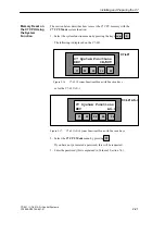
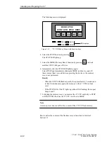
Page 39: ...ns KEY IN OUT F1 F2 F3 F4 F5 Figure 2 16 C7 621 System Functions Menu with Function Keys or for the C7 621 AS i C7Ć621 ASĆi C7 System Functions KEY AS i F1 F2 F3 F4 F5 Figure 2 17 C7 621 AS i System Functions Menu with Function Keys 2 Select the C7 CPU Mode menu by pressing F1 If you have not yet entered a password this will be requested 3 Enter the password this is explained in Volume 2 Section 7...

Page 40: ...erwards MRES within 1 second If there is more than 1 second between pressing the two keys the memory reset is not performed Result When the STOP LED flashes quickly for approximately 3 seconds and is then lit continuously again the memory on the C7 CPU has been reset If the STOP LED of the C7 lights up without first flashing then repeat Steps 4 and 5 7 Following the memory reset you must set the C...

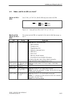
Page 41: ...rror in the internal I O functions To find out the exact cause of the problem read out the diagnostic buffer using a programming device DC5V green 5V DC power supply for the C7 Lights up when the internal 5V DC power supply is functioning correctly FRCE yellow Reserved RUN green RUN or RUNP mode on the C7 CPU Lights up when the C7 is executing the user program Flashes several times during the C7 s...

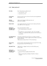
Page 42: ...o the reference manual 235 If the power is turned off the current time is saved in the non volatile memory When power is turned on again the clock continues to run starting from the saved time When the power is turned off the C7 CPU clock itself stops The clock on the C7 OP is independent of the clock on the C7 CPU When the power is turned off the C7 OP clock stops When the device is shipped the c...

Page 43: ...ed with a run time meter This allows you to count the operating hours of the C7 CPU or a resource it controls You program the run time meter in the user program using the SFCs 2 SET_RTM 3 CTRL_RTM and 4 READ_RTM see reference manual 235 Run Time Meter Installing and Preparing the C7 ...

Page 44: ...2 26 C7 621 C7 621 AS i Control Systems C79000 G7076 C621 01 Installing and Preparing the C7 ...

Page 45: ...PI network can communicate with each other you must assign MPI addresses to them How you assign MPI addresses and the rules to be observed are described in the user manual 231 for S7 and in the ProTool documentation for the C7 OP Volume 2 of this manual Section 3 4 10 contains the information you require for configuring communication with specific C7 CPUs Section Description Page 3 1 Communication...

Page 46: ...lf occupies two MPI addresses and therefore represents two nodes as follows One for the C7 CPU One for the C7 OP A segment is a section of the network between two terminating resistors A segment can include up to 32 nodes A segment is also limited by the maximum permitted cable length that depends on the transmission rate see Section 3 3 You can interconnect up to 126 addressable nodes on an MPI n...

Page 47: ...ss must be higher than the highest actual MPI address and must be set to the same value on all nodes Exception connecting a programming device to several nodes see Chapter 4 A CPU can communicate with up to four C7 CPUs or S7 300 CPUs These can exchange shared data with each other For more detailed information about shared data refer to the manual 231 The transmission and reception of shared data ...

Page 48: ... devices and OPs directly in the MPI network This means that only the programming devices or OPs required for installation or maintenance must be connected via tap lines to the MPI network S If you operate more than 32 nodes in a network the bus segments must be connected via RS 485 repeaters S Ungrounded bus segments and grounded bus segments are connected via RS 485 repeaters S Each RS 485 repea...

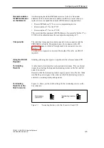
Page 49: ...so Section 3 5 To connect two segments or to extend the length of the cable use RS 485 repeaters Installing and using the repeater is explained in the reference manual 71 A cable must be terminated by its characteristic resistance This is achieved simply by activating the integrated terminating resistor on the first and last node of a network Remember that the terminating resistor requires power t...

Page 50: ...g Resistor on the RS 485 Repeater Figure 3 3 shows a possible MPI configuration in which the terminating resistor must be activated RS 485 repeater Terminating resistor activated S7 300 S7 300 C7 Connecting cable S7 300 OP 25 OP 25 PG PG Only connected during installation maintenance via a tap line À À À À Figure 3 3 Activating Terminating Resistors in an MPI Network Terminating Resistor on the RS...

Page 51: ...cted via a tap line with the default MPI address S7 300 Connected later to the MPI subnet with default MPI address 0 16 0 x MPI addresses of the nodes 11 13 14 15 5 6 7 8 PG OP 25 OP 25 PG OP 25 À À Terminating resistor activated Apart from the MPI address here address 7 the CP also has a PROFIBUS address FM 12 CP 10 PROFI BUS subnet 3 4 9 Figure 3 4 Example of an MPI Subnet Example of an MPI Subn...

Page 52: ...ber of nodes when calculating the number of nodes although it is not assigned its own MPI number Figure 3 5 shows how the cable for an MPI network can be extended using RS 485 repeaters C7 50 m 1000 m 50 m RS 485 repeater PROFIBUS LAN cable remote segment Figure 3 5 Maximum Cable Length Between Two RS 485 Repeaters Tap lines are cables with which the programming devices or OPs can be connected to ...

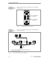
Page 53: ...MPI network RS 485 repeater RS 485 repeater max 50 m max 50 m max 1000 m Terminating resistor activated C7 S7 300 S7 300 S7 300 S7 300 Connecting cable PG connected via tap line for maintenance 0 12 0 x MPI addresses of the nodes 8 9 10 11 3 4 5 6 7 OP 25 PG PG OP 25 OP 25 Remote Segment À À À À À À À Figure 3 6 Cable Lengths in an MPI Network Example Configuring an MPI Network ...

Page 54: ... LAN Cables PROFIBUS LAN cable 6XV1 830 0AH10 PROFIBUS underground cable 6XV1 830 3AH10 PROFIBUS trailing cable 6XV1 830 3BH10 PROFIBUS LAN cable with PE sheath for the food drinks and tobacco industry 6XV1 830 0BH10 PROFIBUS LAN cable for festoons 6XV1 830 3CH10 The PROFIBUS LAN cable is a shielded twisted pair cable with the following characteristics Table 3 4 Characteristics of the PROFIBUS LAN...

Page 55: ...cable the following restrictions must also be taken into account dO outer diameter of the cable Table 3 5 Restrictions when Laying the Interior LAN Cable Characteristics Limits Bending radius bending once w 80 mm 10 dO Bending radius repeated bending w 160 mm 20 dO Permitted temperature range during installation 5 _C to 50 _C Permitted temperature range during storage and when installed 30 _C to 6...

Page 56: ... connectors S Up to 12 Mbps PROFIBUS bus connector 6GK1500 0EA00 S Up to 12 Mbps Without PG interface 6ES7 972 0BA10 0XA0 With PG interface 6ES7 972 0BB10 0XA0 S Up to 12 Mbps with swivelling cable outlet straight or angled Without PG interface 6ES7 972 0BA20 0XA0 With PG interface 6ES7 972 0BB20 0XA0 You do not require a bus connector for the RS 485 repeater Purpose of the Bus Connector No Area o...

Page 57: ... the PROFIBUS network The cable can be connected either from the left or right Switch setting for the first and last station on the PROFIBUS network ON terminating resistor activated The cable shield must lie on the bare metal Figure III Terminator resistor deactivated The cable shield must lie on bare metal II III Figure 3 7 Appearance of the PROFIBUS Bus Connector Appearance 6GK15000 0EA00 Confi...

Page 58: ... PROFIBUS LAN cable 6XV1 830 0AH10 Figure 3 8 Connecting the PROFIBUS LAN Cable to the Screw Terminal Block 3 5 2 Bus Connector 6ES7 972 0B 20 0XA0 Figure 3 9 shows the bus connector with order number 6ES7 972 0B 20 Screws for securing to the station PG interface only with 6ES7 972 0BB20 0XA0 9 pin sub D connector for connection to the station Casing screw Switch for terminating resistor Hinged cl...

Page 59: ...e Outlet Without PG interface Figure 3 10 Length of Insulation to be Removed when Fitting the Bus Connector 6ES7 972 0B 20 2 Open the casing of the bus connector by undoing the screw and lifting the cover 3 Release the cover of the hinged clamp 4 The bus connector with order number 6ES7 972 0B 20 is shipped with the cable outlet at 30 degrees If you require a vertical cable outlet Loosen the left ...

Page 60: ...us cable connector for the first and last stations on the bus1 Bus cable connection for all other stations on the bus 1 The bus cable can be connected either to the right or left A B A B A B A B ÇÇ ÇÇ Figure 3 11 Fitting the Bus Connector 6ES7 972 0B 20 to the LAN Cable 6 Screw down the hinged clamp again Make sure that the bare cable shield makes contact under the shield clamp 7 Secure the green ...

Page 61: ...ating resistor Interface for PG OP Screws for fixing to the node To connect the bus connector 6ES7 972 0B 10 0XA0 to the PROFIBUS LAN cable follow the steps outlined below 1 Cut the bus cable to the required length 2 Strip the insulation from the bus cable as shown in Figure 3 12 ÇÇ ÇÇ 7 5 9 6 ÇÇ ÇÇ 7 5 9 6 6XV1 830 0AH10 3BH10 6XV1 830 3AH10 16 Figure 3 12 Preparing the LAN Cable for Connecting t...

Page 62: ... sheath between the two clips This fixes the cable in position 7 Tighten the screw terminals for the green and red wires ÇÇ A B A B ÇÇ A B A B ÇÇ Bus cable connection for first and last node on the network LAN cable connection for all other nodes in the network The LAN cable can be connected either to the right or left Figure 3 13 Connecting the LAN Cable to the Bus Connector 6ES7 972 0B 10 0XA0 8...

Page 63: ... always turned on during startup and operation Terminating resistor on Terminating resistor off on off on off Figure 3 14 Bus Connector 6ES7 Terminating Resistor Activated and Deactivated You can remove the bus connector with a LAN cable connected through at any time from the PROFIBUS DP interface without interrupting the data exchange on the bus Warning Disturbance of data exchange on the bus is ...

Page 64: ...3 20 C7 621 C7 621 AS i Control Systems C79000 G7076 C621 01 Configuring an MPI Network ...

Page 65: ...ol Systems C79000 G7076 C621 01 Connecting a Programming Device PC to a C7 Section Description Page 4 1 Connecting a Programming Device PC to a C7 4 2 4 2 Connecting a Programming Device PC to Several Nodes 4 3 Chapter Overview 4 ...

Page 66: ...ction 3 3 You can connect a programming device or PC to the MPI port of the C7 using a preassembled PG cable As an alternative you can use PROFIBUS LAN cable and bus connectors to make your own connecting cable see Section 3 5 Figure 4 1 shows the components for connecting a programming device PC to a C7 PG cable PG PC C7 Figure 4 1 Connecting a Programming Device PC to a C7 Possibilities Cable Le...

Page 67: ...the programming device PC in the MPI network S Programming device PC connected only for installation and maintenance work Depending on the network attachment you connect the programming device PC with other nodes as follows see also Section 3 2 Network Attachment Connection Programming Device PC installed permanently in the network The programming device PC is included directly in the MPI network ...

Page 68: ... programming device PC we recommend the following procedure To attach a programming device PC to an MPI network with an Unknown node address it is advisable to set the following address on the service programming device PC S MPI address 0 S Highest MPI address 126 Following this use the STEP 7 function Hardware Configuration to find out the highest MPI address in the MPI network and then set the h...

Page 69: ...ap line The bus connector of this node must have a PG interface see also Section 3 5 Figure 4 3 shows two networked C7s to which a programming device PC is connected PROFIBUS LAN cable PG cable tap line C7 PG PC C7 Figure 4 3 Attaching a Programming Device PC to an MPI Network Programming Device PC for Installation or Maintenance Connecting a Programming Device PC to a C7 ...

Page 70: ...odes must be connected to bus segment 2 if the PG is connected to bus segment 1 terminals A1 B1 or the programming device OP interface see Chapter 7 in the reference manual Module Data Figure 4 4 shows the RS 485 repeater as an interface between a grounded and an ungrounded node in an MPI subnet C7 Bus segment 2 signals ungrounded PG Bus segment 1 signals grounded Figure 4 4 PG Connected to an Ung...

Page 71: ...5 1 C7 621 C7 621 AS i Control Systems C79000 G7076 C621 01 Attaching a C7 621 AS i Note The information in this chapter applies only to the C7 621 AS i 5 ...

Page 72: ...s AS i and AS i Connect the power supply unit either directly to the C7 621 AS i or supply power to the AS i CP in the C7 621 AS i by connecting the AS i power supply in the network with the actuators or sensors Figure 5 1 shows the connections and block diagram of the AS i terminals AS i terminals Block diagram of the AS i terminals View from the right side of the C7 621 AS i Sensor 1 AS i power ...

Page 73: ...y have been connected to the AS i cable this can be done without any problem The AS i cable is self healing This means that the holes made by the contacts penetrating the jacket close automatically and re establish degree of protection IP67 When the cable is installed in an AS i module the cable seals the cable inlets This allows degree of protection IP67 to be achieved Apart from the special AS i...

Page 74: ...5 4 C7 621 C7 621 AS i Control Systems C79000 G7076 C621 01 Attaching a C7 621 AS i ...

Page 75: ...1 01 C7 621 Digital I Os Section Description Page 6 1 Digital Inputs 6 2 6 2 Digital Outputs 6 4 6 3 Status Displays of the DI DO 6 7 Note The information this chapter applies only to the C7 621 The C7 621 AS i does not have digital I Os Chapter Overview 6 ...

Page 76: ...roximity switches BEROs Figure 6 1 shows the terminals and block diagram of the digital inputs Pin name 0 0 0 1 0 2 0 3 0 4 0 5 0 6 0 7 These shaded sections are irrelevant for this example Digital inputs 1 0 1 1 1 2 1 3 1 4 1 5 1 6 1 7 Block diagram of an input Bottom view of the C7 621 L M NC NC Input DC 24V Figure 6 1 Terminals and Block Diagram of the Digital Inputs Characteristics Terminals a...

Page 77: ...mber of simultaneously accessible inputs 16 Floating no Status Interrupt Diagnostics Interrupts no Diagnostic functions no Data for Selecting a Sensor Input voltage S Rated value S For signal 1 S For signal 0 DC 24 V 11 to 30 V 3 to 5 V Input current S For signal 1 Typically 7 mA Input delay S From 0 to 1 S From 1 to 0 1 2 to 4 8 ms 1 2 to 4 8 ms Input characteristics Complying with IEC 1131 Type ...

Page 78: ... outputs non floating S Output current 0 5 A S Rated load voltage 24V DC S Suitable for example for solenoid valves and DC contactors When the power supply is turned on the digital output applies a pulse to the outputs Within the permitted output current range a pulse can be approximately 50 s long Properties Note C7 621 Digital I Os ...

Page 79: ...led technical data about the digital outputs Pin name Shaded sections are irrelevant for this example Digital outputs 0 0 0 1 0 2 0 3 0 4 0 5 0 6 0 7 1 0 1 1 1 2 1 3 1 4 1 5 1 6 1 7 Bottom view of the C7 621 L M NC NC Input DC 24V Block diagram of an output Figure 6 2 Terminals and Block Diagram of the Digital Outputs Terminals and Block Diagram C7 621 Digital I Os ...

Page 80: ...utput voltage S At signal 1 min L 0 8 V Output current S For signal 1 Rated value Permitted range S For signal 0 residual current 0 5 A 5 mA to 0 6 A max 0 5 mA Load resistance range 48 W to 4 kW Lamp load max 5 W Parallel connection of 2 outputs S For redundant activation of a load S For increased power Possible only outputs of the same group Not possible Activation of a digital input Possible Sw...

Page 81: ...lected in the system functions menu by pressing the key The following data are displayed Anwahl der DI 11101110 00001010 DO 10101010 11010001 Bit 0 7 Bit 0 0 Bit 1 7 Bit 1 0 Figure 6 3 Example of a Status Display on a C7 621 Table 6 1 Explanation of the DI DO Status Display in Figure 6 3 Display Explanation 1 0 DI DO set DI DO reset Note The values of the DI DO are read in at one second intervals ...

Page 82: ...6 8 C7 621 C7 621 AS i Control Systems C79000 G7076 C621 01 C7 621 Digital I Os ...

Page 83: ...nsors 7 5 7 2 Connecting Loads Actuators to the Analog Output 7 7 7 3 Analog Input 7 10 7 3 1 Properties and Technical Data of the Analog Input 7 11 7 4 Analog Output 7 15 It is not possible to include the C7 in an ungrounded configuration Note The information in this section applies only to the C7 621 The C7 621 AS i does not have analog I Os Chapter Overview Ungrounded Configuration 7 ...

Page 84: ... it is possible that the permitted value for UCM will be exceeded or if you cannot measure the potential difference exactly you must connect AIx M with M This also applies to unused inputs The following abbreviations are used in Figures 7 1 to 7 4 AIx X Measuring cable AIx U or AIx I AIx M Reference potential of the measuring cable M Chassis connection of C7 621 and Reference potential of the anal...

Page 85: ...or noise potential differences static or dynamic can occur between the locally distributed measuring points To avoid these potential differences you should install equipotential bonding cables between the measuring points Potential differences UCM static or dynamic can also occur between the measuring cables AIx M of the input channels and the reference point of the measuring circuit M This potent...

Page 86: ...ated sensors to a floating analog input module Isolated sensor Input 24V DC Grounding bar ADC Logic AI1 U AI1 M C7 CPU U UCM AI2 U AI2 M U L M NC NC Analog inputs Functional earth M C7 621 Equipotential bonding cable Figure 7 2 Connecting Non Isolated Sensors to a Floating Analog Input C7 621 Analog I Os ...

Page 87: ...x M Measuring cable reference potential M Reference potential of the analog measuring circuit functional ground Figure 7 3 shows the connection of voltage sensors to a non floating analog input ADC Logic AI1 U AI1 M C7 CPU U AI2 U AI2 M U Analog inputs Functional ground M C7 621 Figure 7 3 Connecting Non Isolated Sensors to a Non Floating Analog Input Abbreviations Connecting Voltage Sensors C7 62...

Page 88: ... a non floating analog input Sensor e g pressure meas Input 24V DC Grounding bar ADC Logic AI1 U AI1 M C7 CPU AI2 U AI2 M L M NC NC Analog inputs Functional ground M C7 621 UH transducer 4 wire P P Figure 7 4 Connecting 4 Wire Transducers to a Non Floating Analog Input Note 2 wire transducers cannot be operated with the C7 units Connecting Sensors as 4 Wire Transducers C7 621 Analog I Os ...

Page 89: ...equipotential current can flow through the shield and cause disturbances to the analog signals In this case you should only ground the cable at one end The abbreviations used in Figures 7 5 to 7 6 have the following meaning AO I Analog output current AO U Analog output voltage RL Load actuator AO M Chassis connection reference potential of the analog output L Power supply connection 24 V DC M Chas...

Page 90: ...ce point of the analog circuit Figure 7 5 shows the connection of loads to a current output of a non floating analog output module C7 CPU DAC RL AO I Logic AO M Input 24V DC L M NC NC Functional ground M C7 621 Figure 7 5 Connecting Loads to a Current Output of a Non Floating Analog Output Connecting Loads to a Current Output C7 621 Analog I Os ...

Page 91: ...og output AO U and the reference point of the measuring circuit AO M Figure 7 6 shows the connection of loads to a voltage output of a non floating analog output module with a 2 wire connection C7 CPU DAC RL AO U Logic AO M Input 24V DC L M NC NC Functional ground M C7 621 Figure 7 6 Connection of Loads to a Voltage Output of a Non Floating Analog Output Module Connecting Loads to a Voltage Output...

Page 92: ... Which measuring ranges are provided by the analog input module The following measurement types are possible on the analog input module S Voltage measurement S Current measurement The measurement ranges are as follows S Voltage 10V S Current 20mA The measuring ranges for current measurement with 4 wire measuring transducers are as follows S 20mA Contents Selectable Types of Measurement Measurement...

Page 93: ...nical Data of the Analog Input Module The analog input module has the following properties S 4 inputs S Measured value resolution 12 bits including sign S Measurement type selected by wiring Voltage Current S Measuring range selected per input S Non floating Properties C7 621 Analog I Os ...

Page 94: ...2 U AI2 I AI2 M AI3 U AI3 I AI3 M AI4 U AI4 I 2 1 3 V 5 4 6 V 8 7 9 V 11 10 12 V Current measurement 2 1 3 5 4 6 8 7 9 11 10 12 AI4 M View from the right of the C7 621 These shaded sections are irrelevant for this example Figure 7 7 Terminal Diagram of the Analog Inputs For more information about analog addresses refer to Volume 2 Chapter 4 Terminal Diagram Analog Addresses C7 621 Analog I Os ...

Page 95: ...3 I Current input Channel 3 AI3 AI3 M Reference potential AI4 U Voltage input AI4 I Current input Channel 4 AI4 AI4 M Reference potential Only an analog sensor can be connected to an analog input channel Voltage Measurement Current Voltage Reference potential NjSingle channel voltage measurement Figure 7 8 Connection of a Channel for Voltage Measurement Current Measurement Current Voltage Reference...

Page 96: ...put range S Voltage input S Current input 1 0 1 0 Noise Suppression Error Limits continued Basic error limit operational limit at 25 C relative to input range S Voltage input S Current input 0 9 0 8 Temperature error relative to input range 0 01 K Linearity error relative to input range 0 06 Reproducibility accuracy in settled state at 25 C relative to input range 0 06 Status Interrupts Diagnostic...

Page 97: ...dule You will learn the following S How to install and start up an analog output module S Which ranges are provided by the analog output module S The technical data for the analog output module The analog output module has the following properties S 1 Output S The output can be selected as Voltage output Current output S Resolution 12 bits including sign Contents Properties C7 621 Analog I Os ...

Page 98: ...ram of the analog output module Pin name View from the right of the C7 621 AO U AO I AO M Analog output Connection Current output Voltage output 15 14 16 V A These shaded sections are irrelevant for this example Figure 7 10 Terminal Diagram of the Analog Outputs Terminal Diagram C7 621 Analog I Os ...

Page 99: ...or related to output range 0 06 Reproducibility accuracy in settled state at 25 C related to output range 0 05 Output ripple Range 0 to 50 kHz related to output range 0 05 Status Interrupts Diagnostics Interrupts none Diagnostic functions none Data for Selecting an Actuator Output ranges rated values S Voltage S Current 10 V 20 mA Load resistance S For voltage output Capacitive load S For current ...

Page 100: ...7 18 C7 621 C7 621 AS i Control Systems C79000 G7076 C621 01 C7 621 Analog I Os ...

Page 101: ...8 1 C7 621 C7 621 AS i Control Systems C79000 G7076 C621 01 Maintenance 8 ...

Page 102: ...e the user program from the C7 CPU on a programming device PC using STEP 7 If the C7 CPU is defective and the user program can no longer be read remove the C7 without attempting to back up the data S The configuration loaded on the C7 cannot be read This must be available on a programming device or PC As soon as you have a new C7 available install it as follows 1 Mechanical and electrical installa...

Page 103: ...ese general technical specifications include the standards with which the C7 complies the test values that it meets and the test criteria with which the C7 was tested Section Description Page A 1 Technical Specifications A 2 A 2 Notes on the CE Approval A 5 A 3 Notes for Manufacturers of Machines A 7 What are General Technical Specifications Chapter Overview A ...

Page 104: ...1 23 keys P bus C7 621 Interface to S7 300 modules MPI interface Standard MPI interface C7 OP Flash memory configuration memory C7 621 128 Kbytes C7 621 AS i 128 Kbytes C7 621 ASi CP Bus cycle time 5 ms with 31 slaves Connection of the AS i cable Current load between terminals Ai and Ai maximum 4A ASi CP current consumption max 100 mA ASi CP supply voltage from the ASi cable According to the AS i ...

Page 105: ...EC 1000 4 2 ESD 8kV atmospheric discharge complying with IEC 801 2 IEC 1000 4 2 ESD Noise immunity against discharge C7 621 ASi 4kV discharge on contact complying with IEC 801 2 IEC 1000 4 2 ESD 8kV atmospheric discharge complying with IEC 801 2 IEC 1000 4 2 ESD Immunity to high frequency radiation 10V with 80 amplitude modulation with 1 kHz 10kHz to 80MHz complying with EN 50 141 10V m with 80 am...

Page 106: ...erating voltage load voltage relay power supply etc must be provided as a safety extra low voltage SELV Warning Danger of personal injury and damage to equipment If you do not implement the 24 V DC power supply for the C7 621 or C7 621 ASi correctly this may result in damage to components of your automation system and to personal injury Use only safety extra low voltage SELV for the 24 V DC power ...

Page 107: ...a EN 50081 2 1993 EN 50082 2 1995 Domestic area business and trade area and small plants EN 50081 1 1992 EN 50082 1 1992 The EU conformity declarations are kept according to the EU directives listed above for the authorities responsible at the following address Siemens Aktiengesellschaft Bereich Automatisierungstechnik AUT 125 Postfach 1963 D 92209 Amberg The installation guidelines and safety ins...

Page 108: ...due to integration in ASICs Due to its low levels of toxic materials the SIMATIC C7 621 is suitable for recycling For more information about recycling and disposal of your old SIMATIC unit contact the following department Siemens Aktiensgesellschaft Technische Dienstleistungen ANL A 44 Kreislaufwirtschaft Postfach 3240 D 91052 Erlangen Germany Telefon 0 91 31 7 3 33 19 Telefax 0 91 31 7 2 66 43 Th...

Page 109: ...lectrical equipment of machines Part 1 specification for general requirements applies for electrical equipment in machinery The table below is intended to help you with the declaration of conformity and to show which criteria apply to SIMATIC according to EN 60204 1 as of June 1993 EN 60204 1 Subject Criterion Remarks Paragraph 4 General requirements Requirements are met if the devices are mounted...

Page 110: ...A 8 C7 621 C7 621 AS i Control Systems C79000 G7076 C621 01 General Technical Specifications ...

Page 111: ...ve Devices ESD Section Description Page B 1 What is ESD B 2 B 2 Electrostatic Charging of Objects and Persons B 3 B 3 General Protective Measures Against Electrostatic Discharge Damage B 4 B 4 Taking Measurements and Working on ESD Modules B 6 B 5 Packing Electrostatic Sensitive Devices B 7 Chapter Overview B ...

Page 112: ...ESD Electrostatic sensitive devices are labeled with the following symbol Caution Electrostatic sensitive devices are subject to voltages that are far below the voltage values that can still be perceived by human beings These voltages are present if you touch a component or module without previously being electrostatically discharged In most cases the damage caused by an over voltage is not immedi...

Page 113: ...to 8 000 V S Desoldering device with plastic parts up to 8 000 V S Walking on plastic flooring up to 12 000 V S Sitting of a padded chair up to 15 000 V S Walking on a carpet synthetic up to 15 000 V An electrostatic discharge is S Perceptible from 3500 V S Audible from 4500 V S Visible from 5000 V A fraction of these voltages is capable of destroying or damaging electronic devices Carefully note ...

Page 114: ...you wear a wristband complying with ESD specifications or if you use special ESD footwear or ground straps when walking on an ESD floor S Persons working on electronic devices should first discharge their bodies by touching grounded metallic parts e g bare metal parts of switchgear cabinets water pipes etc S Protect the modules against contact with chargeable and highly insulating materials such a...

Page 115: ...ns for handling electrostatically sensitive devices a Conductive flooring material b Table with conductive grounded surface c ESD footwear d ESD smock e Grounded ESD wristband f Grounded of switchgear closet g Grounded chair a b c d e f g ESD Precautions Guidelines for Handling Electrostatically Sensitive Devices ESD ...

Page 116: ...aken on electrostatic sensitive devices only if S The measuring device is grounded e g via protective conductor or S The tip of the isolated measuring device has previously been discharged e g by briefly touching grounded metal parts Use Grounded Measuring Devices Only Guidelines for Handling Electrostatically Sensitive Devices ESD ...

Page 117: ...d plastic boxes or metal cans Always store ESD modules in conductive packing material When packing modules incorporating batteries cover the battery connections with insulating tape or insulating material to avoid short circuiting of the battery Remove the battery if possible Using Conductive Material for Packing Modules without Casing Cover Batteries Guidelines for Handling Electrostatically Sens...

Page 118: ...B 8 C7 621 C7 621 AS i Control Systems C79000 G7076 C621 01 Guidelines for Handling Electrostatically Sensitive Devices ESD ...

Page 119: ...rn in of all large scale integrated circuits for example processors memory etc S Measures for preventing static charge when handling MOS circuits S Visual checks at all levels of manufacture S In circuit test of all modules in other words computer supported testing of all components and their interaction in the circuit S Continuous tests at increased ambient temperatures over several days S Thorou...

Page 120: ...to a safety and a non safety area In the non safety area there are no particular requirements in terms of safety since failure of the electronics does not affect the safety of the plant or process In the safety area only controllers or circuits can be used that meet the relevant safety regulations Areas are normally divided as follows 1 For controls with few safety requirements for example machine...

Page 121: ...g 234 Programming Manual System Software for S7 300 and S7 400 Program Design 235 Reference Manual System Software for S7 300 and S7 400 System and Standard Functions 236 Manual Function Block Diagram FBD for S7 300 and S7 400 Programming 280 Programming Manual System Software for M7 300 and M7 400 Program Design 1 AS Interface Das Aktuator Sensor Interface für die Automation Werner Kriesel O W Ma...

Page 122: ...1 01 Tel 49 2174 40756 Fax 49 2174 41571 AS i technology is promoted by the AS International Association e V 3 SIMATIC NET Industrial Communications Networks Catalog IK 10 1997 The catalog can be ordered from any SIEMENS office SIMATIC C7 and S7 References ...

Page 123: ...Glossary 1 C7 621 C7 621 AS i Control Systems C79000 G7076 C621 01 Glossary ...

Page 124: ...ctrical conductors or fiber optic cable C Name of the control system family of devices C7 62x The C7 AS i is the C7 component that controls communication with the actuators and sensors via the AS interface It also handles the internal C7 data exchange between the C7 AS i and C7 CPU or C7 OP The C7 CPU central processing unit contains the controller and arithmetic unit memory operating system and p...

Page 125: ...t the first instruction in OB1 Assignment of modules to racks slots and for example in the case of signal modules addresses The configuration memory is a flash memory containing the configuration data and is integrated in the C7 OP Communications processors CPs are intelligent modules with their own processor They form an important group within the components of a programmable controller A distinc...

Page 126: ...same or approximately the same potential as extraneous conducting bodies to prevent interference or hazardous voltages arising between the bodies Error display is one of the possible responses of the operating system to runtime errors The other possible responses are Error response in the user program STOP status of the C7 CPU F FEPROMs correspond in their function to the electrically erasable EEP...

Page 127: ...th the grounding electrode one or more conductive parts that have very good contact to ground via a grounding point H A hardware interrupt is triggered by interrupt triggering modules as the result of certain events in the process The hardware interrupt is signaled to the C7 CPU Depending on the priority of the interrupt the corresponding organization block is then executed I The STEP 7 info funct...

Page 128: ...up memory and the user program is reloaded from the flash memory When you clear the C7 OP the following memories are deleted S The work memory S The configuration memory The C7 OP then no longer contains a user configuration The multipoint interface MPI is the programming device interface of SIMATIC S7 It allows simultaneous operation of several nodes programming devices text displays operator pan...

Page 129: ...one or more per module Each module is supplied from the factory with a default setting that can be modified using the STEP 7 tool S7 Configuration There are static parameters and dynamic parameters Parameter assignment refers to the setting of the behavior of a module In contrast to static parameters dynamic module parameters can be modified during operation by calling an SFC in the user program f...

Page 130: ...ernal bus system The I O and the programming language are designed specifically for the requirements of control engineering Programming devices are essentially personal computers that are compact and portable and suitable for use in industry They are characterized by being equipped with special hardware and software for SIMATIC programmable controllers R Random access memory is a read write memory...

Page 131: ...mplemented in the form of a RAM The address areas for example timers counters memory bits and the data areas required internally by the operating system for example buffers for communications are stored in the system memory T The time delay interrupt belongs to one of the priority classes in program execution on the C7 CPU It is generated after expiry of a time started in the user program The asso...

Page 132: ...he C7 CPU The user program contains all the statements and declarations as well as data for signal processing by which a plant or process can be controlled It is assigned to a programmable module for example C7 CPU FM and can be structured in smaller units blocks V Voltage dependent resistor W The work memory is a RAM in the C7 620 that the processor uses to access the user program during program ...

Page 133: ...the LAN cable 3 15 installing the PROFIBUS LAN cable 3 17 purpose 3 12 removing 3 19 setting the terminating resistor 3 19 terminating resistor 3 5 C C7 installing 2 3 range of functions 1 2 1 3 C7 accessories 2 2 C7 CPU Glossary 2 clock 2 24 memory reset 2 21 C7 minimum clearance 2 6 C7 OP Glossary 3 clock 2 24 Cable for analog signals 7 2 7 7 Cable lengths in an MPI network 3 8 maximum 3 8 CE ap...

Page 134: ...able with bus connector order no 6ES7 3 15 with PROFIBUS bus connector 3 14 Installing C7 2 3 Interference signals 2 13 K Keying connectors 2 16 M Machines with SIMATIC A 7 Male and female connectors view 2 7 Manufacturers of machines A 7 Master clock 2 24 Measurement ranges analog input 7 10 Memory reset C7 CPU 2 21 Minimum clearance C7 2 6 MPI 3 2 MPI address 3 2 highest 3 2 of the C7 3 3 recomm...

Page 135: ...nating resistor 3 6 using 3 5 RUN 2 23 Run time meter 2 25 S S7 300 CPU 1 5 Securing post fitting 2 4 releasing 2 5 Sensor non isolated 7 3 Sensors isolated 7 2 SF 2 23 Shared data 3 3 Shield clip 2 15 Shielding 2 13 Signal modules 1 5 Status display 6 7 DI DO 6 7 STOP 2 23 System functions menu quitting 6 7 T Tap line 3 4 3 8 Terminating resistor 3 4 3 5 bus connector order no 6ES7 3 19 example 3...

Page 136: ...Index 4 C7 621 C7 621 AS i Control Systems C79000 G7076 C621 01 Index ...

Page 137: ...Plastic Pulp and Paper Textiles Transportation Other _ _ _ _ _ _ _ _ _ _ _ From Your Name _ _ _ _ _ _ _ _ _ _ _ _ _ _ _ _ _ _ _ _ _ _ _ _ _ _ _ _ _ Your Title _ _ _ _ _ _ _ _ _ _ _ _ _ _ _ _ _ _ _ _ _ _ _ _ _ _ _ _ _ Company Name _ _ _ _ _ _ _ _ _ _ _ _ _ _ _ _ _ _ _ _ _ _ _ _ _ _ Street _ _ _ _ _ _ _ _ _ _ _ _ _ _ _ _ _ _ _ _ _ _ _ _ _ _ City Zip Code_ _ _ _ _ _ _ _ _ _ _ _ _ _ _ _ _ _ _ _ _ _ _ ...

Page 138: ... _ _ _ _ _ _ _ _ _ _ _ _ _ _ _ _ _ _ _ _ _ _ _ _ _ _ _ _ _ _ _ _ _ _ _ _ _ _ _ _ _ _ _ _ _ _ _ _ _ _ _ _ _ _ _ _ _ _ _ _ _ _ _ _ _ _ _ _ _ _ _ _ _ _ _ _ _ _ _ _ _ _ _ _ _ _ _ _ _ _ _ _ _ _ _ _ _ _ _ _ _ _ _ _ _ _ _ _ _ _ _ _ _ _ _ _ _ _ _ _ _ _ _ _ _ _ _ _ _ _ _ _ _ _ _ _ _ _ _ _ _ Remarks Form Your comments and recommendations will help us to improve the quality and usefulness of our publications...

Reviews: