5-12
CM35 Counter Module
(4) J31069-D0416-U001-A5-7618
Parameter block 2
contains:
S
The comparison or start values for channels 7 and 8
S
The bit--coded settings
-- For the switching reaction of the outputs
-- For the direction of counting
-- For the counting value after counter stop
-- For interrupt generation
-- For selection of scanning rate
S
The scanning rate factors for channels 1 to 6
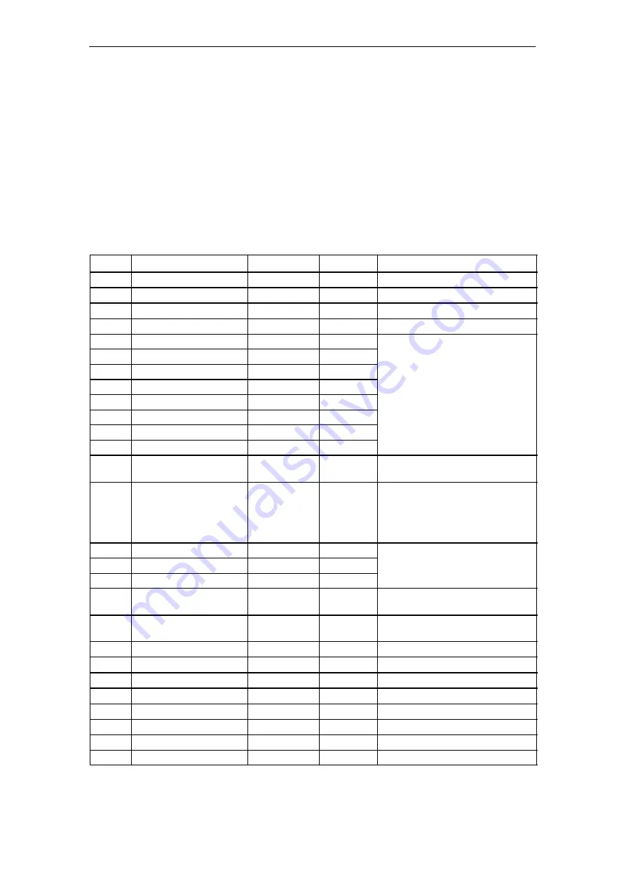
Table 5-10
Parameter block 2
Address
Name
Type
Initial Value
Commentary
Para_Block_2_Data
STRUCT
+0.0
Control_word
WORD
W#16#21
Parameter block no. 2/counter mode
+2.0
Cmp_Start_Value_Chan_7
WORD
W#16#00
Comparison value/start value, channel 7
+4.0
Cmp_Start_Value_Chan_8
WORD
W#16#00
Comparison value/start value, channel 8
+6.0
DO_Mode_Chan_1
BOOL
FALSE
DO mode:
0 = Automatic
+6.1
DO_Mode_Chan_2
BOOL
FALSE
1 = CPU control
+6.2
DO_Mode_Chan_3
BOOL
FALSE
+6.3
DO_Mode_Chan_4
BOOL
FALSE
+6.4
DO_Mode_Chan_5
BOOL
FALSE
+6.5
DO_Mode_Chan_6
BOOL
FALSE
+6.6
DO_Mode_Chan_7
BOOL
FALSE
+6.7
DO_Mode_Chan_8
BOOL
FALSE
+7.0
C_Direction
BOOL
FALSE
Counting direction: 0 = Up
1 = Down
+7.1
Enable_Mode
BOOL
FALSE
Enable mode:
(only applicable to
²
automatic
²
DO
mode)
0 = Continuous enable
1 = Enable control by DO byte
+7.2
Reserve_1
BOOL
FALSE
Reserved
+7.3
Reserve_2
BOOL
FALSE
+7.4
Reserve_3
BOOL
FALSE
+7.5
Delete_CountVal
BOOL
TRUE
Delete counting value: 0 = At stop
1 = At start
+7.6
Interrupt_Generation
BOOL
FALSE
Interrupt generation:
0 = none,
1 = active
+7.7
ScanningRate
BOOL
FALSE
Scanning rate: 0 = no, 1 = yes
+8.0
ScanRate_F_Chan_1
BYTE
B#16#0
Encoder Scanning rate, channel 1
+9.0
ScanRate_F_Chan_2
BYTE
B#16#0
Encoder Scanning rate, channel 2
+10.0
ScanRate_F_Chan_3
BYTE
B#16#0
Encoder Scanning rate, channel 3
+11.0
ScanRate_F_Chan_4
BYTE
B#16#0
Encoder Scanning rate, channel 4
+12.0
ScanRate_F_Chan_5
BYTE
B#16#0
Encoder Scanning rate, channel 5
+13.0
ScanRate_F_Chan_6
BYTE
B#16#0
Encoder Scanning rate, channel 6
=14.0
END_STRUCT
Pulse Counter Operating Mode
Summary of Contents for SIMATIC CM35
Page 1: ...SIMATIC Counter Module CM35 Manual Release 06 2000 ...
Page 9: ...vi CM35 Counter Module 4 J31069 D0416 U001 A5 7618 Table of Contents ...
Page 10: ...1 1 CM35 Counter Module 4 J31069 D0416 U001 A5 7618 Product Overview 1 ...
Page 20: ...2 1 CM35 Counter Module 4 J31069 D0416 U001 A5 7618 Function Description 2 ...
Page 23: ...2 4 CM35 Counter Module 4 J31069 D0416 U001 A5 7618 Function Description ...
Page 47: ...3 24 CM35 Counter Module 4 J31069 D0416 U001 A5 7618 Commissioning ...
Page 48: ...4 1 CM35 Counter Module 4 J31069 D0416 U001 A5 7618 Data Communication with the CM35 4 ...
Page 70: ...5 1 CM35 Counter Module 4 J31069 D0416 U001 A5 7618 Pulse Counter Operating Mode 5 ...
Page 98: ...7 1 CM35 Counter Module 4 J31069 D0416 U001 A5 7618 Timer Operating Mode 7 ...
Page 112: ...8 1 CM35 Counter Module 4 J31069 D0416 U001 A5 7618 Positioning Operating mode 8 ...
Page 131: ...8 20 CM35 Counter Module 4 J31069 D0416 U001 A5 7618 Positioning Operating mode ...
Page 133: ...A 2 CM35 Counter Module 4 J31069 D0416 U001 A5 7618 Literature ...
Page 134: ...B 1 CM35 Counter Module 4 J31069 D0416 U001 A5 7618 EC Declaration of Conformity B ...
Page 135: ...B 2 CM35 Counter Module 4 J31069 D0416 U001 A5 7618 EC Declaration of Conformity ...
Page 141: ...Glossary 6 CM35 Counter Module 4 J31069 D0416 U001 A5 7618 Glossary ...


