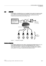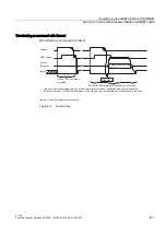
Brief description of ASM hardware
A.6 ASM 854
FC 45
A-24
Function manual, Release 03/2006 , J31069-D0167-U001-A2-7618
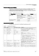
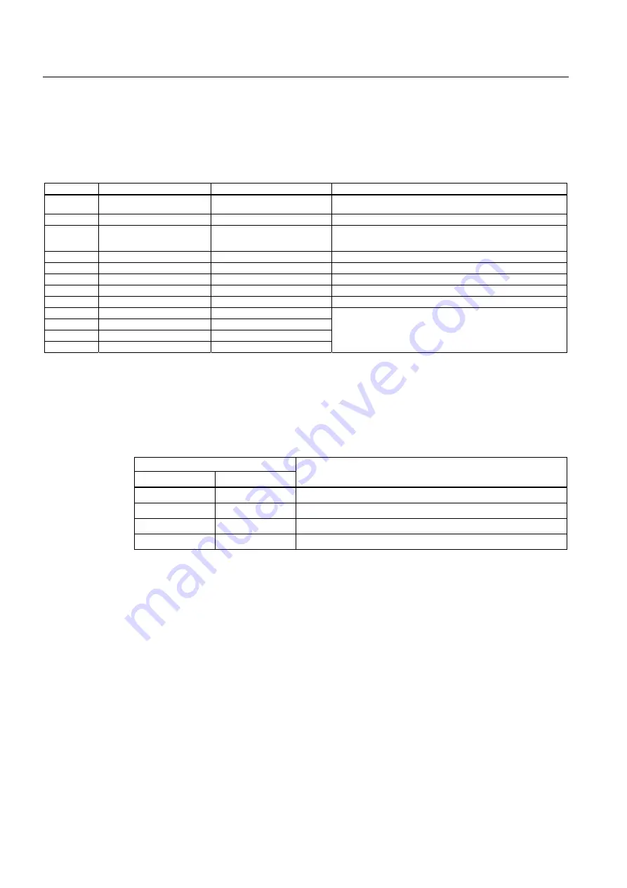
Input parameters for ASM 854
The assignment is made in UDT 10 (see Section "Parameter data block").
Table A-16 Input parameters for ASM 854
Address
Name
Permissible values
Comment
+0.0
ASM_address
256, 264, 272, 280,
...
Each ASM 854 occupies 8 byte of I/O in
the I/O area of the control unit
+2.0
ASM_channel
1, 2, 3, 4
4 parallel channels
+8.0
MDS_control
B#16#0, 1
0 = no presence check
1 = presence check (must always be set
when using MOBY_mode = A (MDS F1xx))
+9.0
ECC_mode
FALSE
No ECC driver
+9.1
RESET_long
FALSE
(no MOBY U)
+10.0
MOBY_mode
B#16#A, B
Only MOBY F parameterization
+11.0
scanning_time
B#16#00
No parameterization of the scanning time
+12.0
option_1
B#16#00, 01, 04, 08
(See Section "INPUT parameters")
+13.0
distance_limiting
B#16#0
+14.0
multitag
B#16#1
+15.0
field_ON_control
B#16#0
+16.0
field_ON_time
B#16#0
Not relevant (no MOBY U)
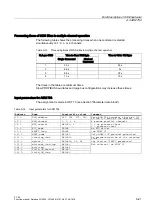
Table of commands for ASM 854
The assignment is made in UDT 20 using the "Command" variable (see Section "Command
parameter settings").
Table A-17 Commands of the ASM 854 when MOBY_mode = B
Command code
normal
Chained
Description
01
41
Write to MDS
02
42
Read MDS
03
43
Initialize MDS
0A
4A
Antenna on/off
The command table is valid for the FB 45. No commands are transferred to the ASM when
fixed-code MDSs are processed with the process image.
Special features of the fixed-code MDS (MOBY_mode = A)
When in this mode, the ASM
automatically reads each new MDS as it arrives. The user does
not need to start a command.
The user issues the read command using UDT 20. repeat_command and command_start
must then be issued simultaneously to start the command and fetch the data.
Switch settings, interfaces and indicators of the ASM 854
See Section "Switch settings, interfaces and indicators of the ASM 454" in Chapter "ASM
454"


