Parameterizing
3.3 Presence check and MDS control
FC 45
3-26
Function manual, Release 03/2006 , J31069-D0167-U001-A2-7618
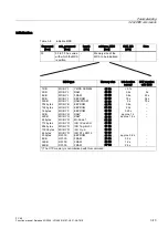
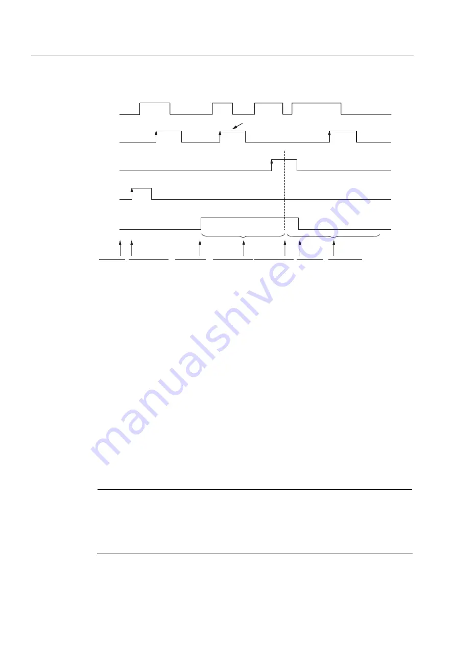
Time diagram
$GGLWLRQDOFRPPDQGVRSWLRQDO
൹7KHVHHGJHVPXVWEHFRQWUROOHGE\WKHXVHU
$SSO\
SRZHU
VXSSO\WR
$60
5(6(7
FRPPDQGDIWHU
$60VVWDUWXS
PHVVDJHQR
0'6SUHVHQW
0'6HQWHUV
ZULWHUHDG
GHYLFHV
ILHOG
5HDGZULWH
FRPPDQGV
DUHH[HFXWHG
E\
ZULWHUHDG
GHYLFH
$60KDV
UHFHLYHGD
1(;7
FRPPDQG
0'6
OHDYHV
ZULWHUHDG
GHYLFHV
ILHOG
$FRPPDQG
IRUDQHZ
0'6FDQEH
VWDUWHGE\WKH
)&)%
$1=B0'6BSUHVHQW
UHDG\
FRPPDQGBVWDUW
5($'
FRPPDQGBVWDUW
1(;7
LQLWBUXQ
Figure 3-4
Time diagram for MDS_control = 2
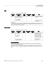
ASM error messages
Error 01 hex: The MDS leaves the write/read device's field while a command is being
processed with this MDS. The command is aborted. The read data are
invalid. With a write command, the data on the MDS may be inconsistent.
Error 02 hex: No command is active on the ASM. During this time, an MDS passes
through the write/read device's field shown above or command processing
of the MDS is not concluded with NEXT. The error is reported during the
next FC 45 command.
Notice
•
The ASM is unable to determine whether an MDS passed through the complete field or
whether the MDS moved into the field briefly and then backed out again.
•
When using field scanning, it is essential to maintain the distance between two write/read
devices specified in the configuration guidelines (see manual on configuration, installation
and service).


