98
13.1
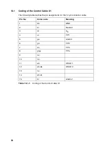
Coding of the Control Cable X1
The following table defines the pin assignments for the 12-pin connector cable
Table 13.1-1:
Coding of the Control Cable X1
Pin No.
Color code
Meaning
1
bk
GND
2
bl
Restart
3
rd
U
B
4
or
FP 1
5
ge
Alarm 1
6
gn
FP 2
7
vio
FP 3
8
gray
FP 4
9
n.c.
10
n.c.
11
wh
OSSD 1
12
wh-bk
OSSD 2
13
n.c.
14
wh-br
15
br
Alarm 2
Summary of Contents for SIMATIC FS600
Page 2: ...600672 ...
Page 109: ...109 ...

