background image

52

5.7

Safeguarding Mobile Machines

Please comply with the safety notes in Chapter 3.

5.7.1

The Purpose of Safeguarding

is for protection:

to protect people when entering variable danger zones

to protect objects located in the vehicle path

to protect the automatic guided vehicle and its load

5.7.2

Installing adjacent laser scanners

The SIMATIC FS600 Laser Scanner has been developed in a way that prevents several
laser scanners from interfering with one other as much as possible. 

5.7.3

Mounting Position

For the purpose of safeguarding the path of a vehicle, the SIMATIC FS600 Laser
Scanner is mounted on the front of a vehicle (in each direction of travel), preferably in
the center. 

The scanner, and hence the beam axis, must be aligned horizontally in order to achieve
a consistent scanning height. 

Please comply with the safety notes in Chapter 3.7.

5.7.4

Mounting Height

As a rule, the scanner should be mounted as low as possible in order to prevent people
from crawling beneath the detection zone. This specification is limited due to such
factors as uneven floors or the deflection of the springs in the AGV.

The maximum mounting height must be selected so that an object (cylinder with a
diameter of 200 mm in the prone position) is reliably detected (see DIN EN 1525). The
detection must be tested at the position of maximum depth within the detection zone. For
AGV applications, sufficient resolution of detection is achieved when an object (upright
cylinder) with a diameter of 70 mm can be detected throughout the detection zone.

WARNING

An increase in the response time can, however, be caused by the installation of several 
adjacent laser scanners. If 

none

 of the constructive measures (section 5.2.1) described 

in the following sections or the specific adjustment (section 5.2.2) are implemented, 

then the SIMATIC FS600 Laser Scanner response time set and shown in the 
configuration and diagnosis software (SIMATIC FS600 Parameterization 
Software LS4soft) is extended by 40 ms.

 This extension in the response time MUST 

be taken into account when calculating the safety distance!

Summary of Contents for SIMATIC FS600

Page 1: ...SIMATIC FS600 Laser Scanner Laser Scanner for Personal Protection and Measurement Tasks Instruction Manual ...

Page 2: ...600672 ...

Page 3: ...s instruction manual and in all documents mentioned herein before any installa tion attempt For any question please refer to your local SIEMENS dealer Important This instruction manual must accompany the product throughout its working life Those persons responsible for the product must ensure that all persons involved in the installation commissioning operation maintenance and servic ing on the pr...

Page 4: ...r will be used A notice warning of injury to persons with a safety alert symbol may also include a warning relating to property damage DANGER indicates that death or severe personal injury will result if proper precautions are not taken WARNING indicates that death or severe personal injury may result if proper precautions are not taken CAUTION with a safety alert symbol indicates that minor perso...

Page 5: ...hose use by third parties for their own purposes could violate the rights of the owner Disclaimer of Liability We have reviewed the contents of this publication to ensure consistency with the hardware and software described Since variance cannot be precluded entirely we cannot guarantee full consistency However the information in this publication is reviewed regularly and any necessary corrections...

Page 6: ...sure its correct overall operation SIEMENS AG its local offices and associated companies hereafter referred to as SIEMENS cannot guarantee for all features of a turn key system or a machine that was not designed by SIEMENS Neither does SIEMENS assume liability for recommendations given in or implied in the following instruction manual The following instruction manual shall not be construed as a ne...

Page 7: ...afeguarding of Automatic Guided Vehicles 26 4 5 Protecting Transporter Trolleys against Collisions 26 4 6 Guarding the sides on AGVs 27 4 7 Other possible applications 28 5 Information for Planning and Mounting 29 5 1 Attachment and Dimensions 30 5 2 Installing adjacent laser scanners 30 5 2 2 Adjusting adjacent laser scanners 31 5 3 Information on Setting the Dimensions of Detection Zones 32 5 3 ...

Page 8: ...Alarm 2 X1 15 67 7 5 OSSD 1 X1 12 and OSSD 2 X1 11 68 7 6 Data Communication 68 8 Integrating the SIMATIC FS600 Laser Scanner into Machine Controls 68 8 1 Integrating the SIMATIC FS600 Laser Scanner with External Wiring with Relays and Quadruple Zone Pair Changeover 69 8 2 Connecting the SIMATIC FS600 Laser Scanner to a Safety Sequence Circuit with Manual Restart Relay Monitoring without Zone Pair...

Page 9: ...11 7 1 General information 91 11 7 2 Initial Measurement of the New Optical Window 93 11 7 3 Procedure when Using the SIMATIC FS600 Parameterization Software LS4soft User Software Version 1 09 or later 94 11 8 Cleaning 95 11 8 1 Cleaning the Optical Window when Dirty 95 11 8 2 Cleaning the Optical Window Cleaning Diffusing Light Panes 96 12 Disposal 97 13 Delivery Package 97 13 1 Coding of the Con...

Page 10: ...0 1 Approvals and Certificates 1 1 Approval and Declaration of EC Conformity EC prototype testing in accordance with DIN EN 61496 1 and IEC 61496 3 TÜV PRODUCT SERVICE GMBH IQSE Ridlerstr 65 80339 Munich ...

Page 11: ...External Device Monitoring Monitoring of external control parts relay monitoring ESPE Electro Sensitive Protecting Equipment FTS Automatic Guided Vehicle see AGV N O Normal open contact OSSD Output Signal Switching Device Safety relevant switch output PC Personal Computer DZ Detection Zone German SF Reset Defined Reset of SIMATIC FS600 Laser Scanner RS 232 RS 232 interface RS 422 RS 422 interface ...

Page 12: ... 336 EWG EMC guideline DIN EN 292 1 and 2 Safety of machinery basic concepts DIN EN 1050 Principles of risk assessment DIN EN 294 Safety distances DIN EN 954 1 Safety related parts of controls DIN EN 999 Approach speeds of body parts DIN EN 60204 1 Electrical equipment of machines DIN EN 60825 1 Safety of machines with laser components DIN EN 61496 1 Electro sensitive protecting equipment IEC 6149...

Page 13: ...emit light pulses within a working range of 190 If these pulses strike a person or an obstacle the reflected light is received and evaluated by the SIMATIC FS600 Laser Scanner The scanner calculates the precise coordinates of the person or object based on the travel time of the reflected light and the current angle of the deflecting unit If the person or obstacle is within the bounds of a previous...

Page 14: ...Laser Scanner can detect people up to a distance of 4 0 m e g 2 15 m even if they are wearing very dark clothing or exhibit a low degree of reflectance Dangerous movements are brought to a standstill by two failsafe semiconductor outputs SF WF a c b f d e DZ Detection zone max 2 15 m 4 m WF Warning zone max 15 m a Maximum registration of measurement values max 50 m b Detection zone programmed in t...

Page 15: ...es Due to its wide range of measurement and its non contact electro sensitive measurement principle the SIMATIC FS600 Laser Scanner can be effectively used as a protective device for virtually any application 2 2 Special Features of the SIMATIC FS600 Laser Scanner Four eight freely programmable detection zones up to a maximum of 4 m Four eight freely programmable warning zones up to a maximum of 1...

Page 16: ...rned off 4 OSSDs are turned on 5a Restart inhibit locked Continuous light 5b Optical window is dirty Light flashing at 2 Hz 5c Fault light flashing at 4 Hz Assignment of interface X1 Assignment of interface X2 as RS232 port Assignment of interface X2 as RS422 port Status displays on the SIMATIC FS600 Laser Scanner Protective caps LEDs FP 4 FP 3 FP 2 Alarm 1 FP 1 UB Restart GND Reserved TxD RxD Res...

Page 17: ... the scanner optical window and the six diffusing light screens The SIMATIC FS600 Laser Scanner is not suitable for use as a protective device if it is possible that dangerous fluids will be spewed out or objects will be ejected for machines with long braking times max depth of the detection zone 4 m For these cases SIEMENS offers suitable safety interlocking devices safety switches with and witho...

Page 18: ...ity with the safety notes in this Connecting and Operating Instruction and in the operating instructions for the SIMATIC FS600 Parameterization Software LS4soft program constitutes part of this expert knowledge The password required for configuring safety relevant parameters must be kept in a secure location by the safety official Information about password levels can be found in the SIMATIC FS600...

Page 19: ...thus detection zone changeover the activation and effect of the detection zone in question must match the alternating operating mode The new detection zone must be activated before turning off the previous detection zone The time at which the changeover is made must be based on a risk analysis Braking paths response and coast down times must be taken into consideration for example overlapping dete...

Page 20: ...in the technical specifications Chapter 14 11 Needle shaped detection zone contours are not permitted since they do not ensure any protective effect For additional information please refer to the SIMATIC FS600 Parameterization Software LS4soft user software Chapter entitled Definition of Detection Zones Due to possible measurement errors every detection zone has an additions area in which detectio...

Page 21: ...is insufficient room available to allow the full dimensions of a detection zone for example because of the position of the scanner additional safety measures e g safety grids must be installed Following each definition of and change to the detection zones the configuration must be checked to see whether the possibility of people standing in the danger zone as well as any barriers provided have bee...

Page 22: ...B of 500 mm to the side of the vehicle on both sides A one sided minimum safety distance is admissible in certain exceptional cases The specifications of DIN EN 1525 must be complied with The basic value of the detection zone width for an AGV corresponds to the maximum vehicle width including the trailer and the dimensions of the load plus the detection zone additions ZS Furthermore the greatest p...

Page 23: ...ing the danger zone or reaching the danger point with their upper and or lower extremities at the same time without impeding the production process The SIMATIC FS600 Laser Scanner can be mounted directly at the machine table or on the side or in front of the machine Fig 4 1 1 Danger area guarding at stationary machinery with two alternating work areas Please comply with the safety notes in Chapter...

Page 24: ...anner must be defined on the basis of a reference boundary In this operating mode the scanner will use the polled environment as a reference and so check for changes in the layout of the protective equipment as well as checking every one of the individual measurements it carries out with a view to detecting an intrusion An example of the configuration of the SIMATIC FS660I Laser Scanner to give ac...

Page 25: ...ection zones In order to safeguard the protective equipment laser scanner and side mounted panels which serve as a reference and provide additional access protection against inadvertent misadjustment or manipulation the detection zones of the SIMATIC FS660I Laser Scanner must be defined on the basis of a reference boundary An example of the configuration of the SIMATIC FS660I Laser Scanner for the...

Page 26: ...Fig 4 4 1 Safeguarding an automatic guided vehicle Please comply with the safety notes in Chapter 3 For an example of how to calculate detection zone measures please refer to Chapter 5 7 9 4 5 Protecting Transporter Trolleys against Collisions Transporter trolleys are generally guided along a system of rails or grooves in the floor Hence the vehicle paths are usually just slightly wider than the t...

Page 27: ...he direction of travel for tolerances in the measurement value and reduced braking power due to wear and tear must be taken into consideration 4 6 Guarding the sides on AGVs In addition to the danger area guarding of the path of an AGV application in some cases it is also necessary to set up a side guarding This side guarding detects people in the space between vehicle and conveyor or detects peop...

Page 28: ...for the side guarding configuration on AGVs can be found inChapter 5 7 9 and 5 7 10 4 7 Other possible applications Object and contour measurement Logistics counting measuring controlling Projection control e g in fully automatic parking ramps or lots Safeguarding or monitoring enclosed spaces and many more ...

Page 29: ... safeguarded e g by safety grids in order to prevent people standing in them from being able to suddenly enter the detection zone This point must be taken into account in the hazard analysis of the machine or system Be sure that there are no retro reflectors or highly reflective surfaces made of metal or ceramic in the area of the detection zone and at the height of the scanning plane Such objects...

Page 30: ...he SIMATIC FS600 Laser Scanner has been developed in a way that prevents several laser scanners from interfering with one other as much as possible 5 2 1 Constructive measures The direct external light irradiation from laser scanners of the same kind 905 nm laser light wavelength in a line and at the same installation height can be prevented with shielding plates at scan level Shielding as high as...

Page 31: ...ers you must install these as shown in the following examples Installation on the basis of the 3RG7838 1AA installation system makes precise adjustment significantly easier Installation with height offset or a crossed alignment also prevents interference from beam reflections onto surrounding objects When safeguarding danger zones please also ensure that it is not possible to crawl under the prote...

Page 32: ...iguration and diagnostic software the SIMATIC FS600 Laser Scanner offers various methods for setting the configurations of detection zones Numerical input A separate dialogue within the user program SIMATIC FS600 Parameterization Software LS4soft allows the right left and front edges of the detection zone to be set using numerical values in mm Graphic input A separate dialogue within the user prog...

Page 33: ...behind the front edge of the scanner 5 3 3 Range of the Warning Zone Resolution A maximum range of 10 meters is available for an object with a diameter of 100 mm The maximum available range for an object with a diameter of 150 mm is 15 m Both of these figures assume a reflectance factor of 20 a Detection zone b Warning zone c Measurement field Fig 5 3 1 Detecting objects in the detection zone and ...

Page 34: ...e SIMATIC FS600 Laser Scanner is equipped with a selectable dust algorithm to ensure optimum freedom from interference The following detection zone additions must be taken into account Activation and deactivation of the function is performed by SIMATIC FS600 Parameterization Software LS4soft Addition ZSM if dust suppression is deactivated 83 mm Addition ZSM if dust suppression is activated 83 mm f...

Page 35: ...2 Mounting Position The SIMATIC FS600 Laser Scanner can be mounted either in a stationary position e g on a wall or a machine or on moving parts e g machine table The qualified installer must ensure that the mounting position of the SIMATIC FS600 Laser Scanner allows the danger zone to be monitored completely If a restart button is being used make certain that the entire detection zone area can be...

Page 36: ...le height range of the SIMATIC FS600 Laser Scanner scanning plane lies between 0 mm Presettings leg detection and 1000 mm above the base level If the application requires a scanning plane higher than 300 mm or if children have access to the area the analysis of the danger zone must consider the hazard caused by persons crawling below the scanning plane 5 4 4 Recommendations for Mounting to Prevent...

Page 37: ...cordingly see Chapter 14 13 and 14 14 The height of the undercut must be limited to prevent people from being able to step beneath it Machine side view Machine view from above a SIMATIC FS600 Laser Scanner S Safety distance b Machine SB Entire width of the c unmonitored zone ST detection zone d Detection zone Z detection zone additions e Height of the undercut ZUMIN depth of the undercut f Mountin...

Page 38: ...es can be optimized by changing the depth at which the scanner is installed or by adjusting the angle range e g from 180 to 190 For information on how to configure the scanner in this way please refer to the SIMATIC FS600 Parameterization Software LS4soft user s manual included with delivery a SIMATIC FS600 Laser Scanner f Lateral access safe b Machine guarding if needed c Lateral Access protectio...

Page 39: ...ner the distance between the detection zone boundary and the machine may not exceed 35 mm Fig 5 4 4 Mounting the scanner across from the machine with an undercut b d c a a SIMATIC FS600 Laser Scanner b Machine c Distance max 35 mm d Detection zone b a d ZUMIN c Z a SIMATIC FS600 Laser Scanner b Machine c Minimum distance from the environment d Detection zone Z Required detection zone additions ZUM...

Page 40: ... Z 83 mm d ZUMIN Depth of the undercut in mm Z Required detection zone additions in mm d Resolution of the scanner d 70 mm This is possible since it is absolutely certain that a person will be detectedin front of the undercut Furthermore the dust algorithm of the SIMATIC FS600 Laser Scanner can be implemented if floating particles may be present in the area This algorithm which can be activated in...

Page 41: ... to a manual approval It affects all detection zones and does not depend on any detection zone changeovers For information on how to configure the scanner appropriately please refer to SIMATIC FS600 Parameterization Software LS4soft Section Safety relevant parameters folder The restart button must be mounted so that the entire danger zone or detection zone area can be viewed from the operating pos...

Page 42: ... of detection or to the detection zone in mm K Approach speed of a person or a person s body parts 1600 mm s in mm s T Lag time of the entire system response time and braking time until standstill in s C Safety related constant to consider entry into the danger zone before the protective device is triggered in mm CMIN Minimum value of the safety related constant 850 mm in mm H Height of the scanni...

Page 43: ...ncluding system and application specific additions in mm K Approach speed of a person or a person s body parts 1600 mm s in mm s TSCAN Response time of the scanner in s TMACH Response time of the machine or system in s TLAG Lag time of the entire system in s LLAG Factor for increase in lag time C Safety related constant in mm 5 4 8 2 Maximum range of detection zone SBDIFF GBDIFF S Z SMAX Maximum r...

Page 44: ...one S Safety distance SB Entire width of the detection zone SBDIFF Largest width of the detection zone SMAX Maximum geometrical distance ST Depth of the detection zone ZAU Detection zone addition application specific Z Detection zone additions ZUMIN Undercut Fig 5 4 5 Considering the maximum measurement distance when safeguarding an area SB SBDIFF c c b d e SMAX Z ST GBDIFF a ZAU S S ZUMIN Z ...

Page 45: ...nstant Response time of the SIMATIC FS600 Laser Scanner adjustable TSCAN 0 08 s Response time of the machine or system TMACH 0 1 s Stopping time or lag time of the machine or system TLAG 0 5 s time for braking the dangerous movement until standstill Factor for increase in lag time LLAG 1 1 fixed addition to account for increased lag time Addition for system specific measurement error ZSM 83 mm whe...

Page 46: ...culation of an undercut This example is based on the following application data If the scanner is mounted across from the machine see Fig 5 4 4 the undercut dimension can be reduced by d 70 mm The formula ZUMIN Z 83 mm d results in a minimum undercut ZUMIN 83 mm 83 mm 70 mm 96 mm It is not allowed for a person to be able to step beneath the undercut Fig 5 4 6 The undercut S MAX S T 22 S BDIFF 2222...

Page 47: ...e of the scanning field limiting the passage and the boundaries of the detection zone must be defined in such a way that no gaps measuring more than 150 mm can arise 5 5 3 Safety relevant settings and calculation of the safety distance To safeguard the protective equipment against inadvertent misadjustment or manipulation the detection zones of the SIMATIC FS660I Laser Scanner must be defined on t...

Page 48: ... distance in mm K Approach velocity in mm s here 1600 mm s T Overall time of delay in seconds a total consisting of Response time of the laser scanner here 80 ms Overtravel time of the machine including the controls Based on measurement of overtravel time C Added margin on account of the possibility of manual intrusion here 850 mm a SIMATIC FS660I Laser Scanner SF1 Detection zone 1 enabled b Refer...

Page 49: ...needs to halt the hazardous movement of the machine or to coordinate the handling of workpieces or their removal from the machine It is best if the laser scanner is firmly installed above the danger zone in such a way that it cannot be manipulated The health and safety officer must ensure that the installation position of the SIMATIC FS660I Laser Scanner does not leave any areas free through which...

Page 50: ...nnection please also have regard to the illustrations given in this chapter S Safety distance in mm K Approach velocity in mm s At a close distance of 500 mm a velocity of 2000 mm s should be assumed If the calculation involves a distance in excess of 500 mm K may be taken to be 1600 mm s But in this case the safety distance is subject to a minimum value of 500 mm T Overall time of delay in second...

Page 51: ... zone must be defined as large enough to ensure an overlapping greater than the tolerance zone of the reference boundary The detection zone will then be constantly monitored so that any body parts intruding or other manipulative intervention will be detected beyond the possibility of doubt In defining the reference boundary please also have regard to the indications given in the Operating Instruct...

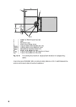
Page 52: ...order to prevent people from crawling beneath the detection zone This specification is limited due to such factors as uneven floors or the deflection of the springs in the AGV The maximum mounting height must be selected so that an object cylinder with a diameter of 200 mm in the prone position is reliably detected see DIN EN 1525 The detection must be tested at the position of maximum depth withi...

Page 53: ...le in Chapter 5 7 6 5 7 5 Recommendations for Mounting to Prevent Unmonitored Zones The creation of unmonitored zones is dependent upon the following factors the vehicle width the design of the vehicle e g attachments shape the position of the scanner the installation depth the selected angle range If the detection zone of a SIMATIC FS600 Laser Scanner mounted on an AGV does not cover the entire f...

Page 54: ...er recess at the front of the vehicle 180 f The protruding attachment results in the creation of unmonitored zones SAB Lateral safety distance between the edge of the roadway and the boundary of the detection zone ZTOT Sum of the system and application specific additions in the direction of travel ZS Sum of the system and application specific additions to the side Fig 5 7 2 Three possibilities for...

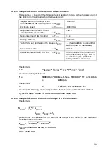
Page 55: ...area Without information from the AGV manufacturer take into account the wear and tear on the brakes by adding an addition LSTOP of at least 10 of the braking distance as long as this is not already included in the braking distance SSTOP If there is a very small distance between the bottom of the AGV and the floor the detection difference between the leg and the toes must be considered in the calc...

Page 56: ...p interlock and or manual restart are included they will not be removed If parameters are set for the function Manual restart the required enable from the startup restart button affects all detection zones and is independent of any detection zone changeover If the current detection zone is manually enabled this enable also applies even if the system switches to another detection zone and this dete...

Page 57: ...avel in mm VMAXAGV Maximum speed of the AGV in mm s TSCAN Response time of the scanner in s TSCAN Response time of the AGV in s LSTOP Factor for wear and tear on the brakes ZTOT Total of the system and application specific additions in the direction of travel in mm ZTOT ZSM ZREFL ZAFLR ZAU ZSM Scanner measurement error in mm ZREFL Addition of the reflectors taken into account in mm ZAFLR Addition ...

Page 58: ...l maximum distances ST Depth of the detection zone ZGES Total of the additions in the direction of travel ZS Total of the additions to the side Fig 5 7 4 Considering the maximum measurement distance for safeguarding AGVs In accordance with DIN EN 1525 a minimum safety distance of 0 5 m width between the vehicle and its environment must be maintained ZGES ZS b d SMAX GBDIFF SBDIFF ST c a ...

Page 59: ...e formula SBDIFF GBDIFF ZS yields under consideration of the width of the danger zone results in the maximum distance to be monitored SBDIFF 1400 mm 83 mm 1483 mm SMAX 2947 mm Largest width of the danger zone from the axis of the rotating mirror GBDIFF 1400 mm Maximum speed VMAXAGV 1800 mm s Response time SIMATIC FS600 Laser Scanner selectable TSCAN 0 08 s Response time of AGV control TAGV 0 1 s B...

Page 60: ...tion of 150 mm is required to detect an entire person This safety relevant setting is automatically set in the SIMATIC FS600 Parameterization Software LS4soft configuration and diagnostics software with selection of the person detection presetting The definition of a reference contour as with access guarding is not necessary as the approach of the person to be protected is made in the direction of...

Page 61: ...r the start must be defined with special consideration of the danger areas valid for this moment The sequence of the monitoring zones to be activated must ensure that the lower threshold of the application related detection zone minimum values is never crossed With selection of zone pair 8 the monitoring function of the scanner is deactivated i e no detection zones are monitored and the safety out...

Page 62: ...ATIC FS600 Parameterization Software LS4soft If these points are not observed the laser scanner will fail within 40 ms and will show this with the additional 2 Hz flashing of the green LED 1 Table 6 1 2 applies with activation start or switchover of zone pairs 1 to 8 Table 6 1 2 Connection of control inputs FP1 to FP4 with activation of zone pairs 1 to 8 Zone pair Control input FP1 FP2 FP3 FP4 1 1...

Page 63: ...e corresponding route segments Also note the safe sequences of changeovers and starts For information on programming the startup detection zones detection zones enabled for starting up the scanner and on determining the sequence in which the detection zones are to be activated please see the SIMATIC FS600 Parameterization Software LS4soft user s manual FP 1 x detection zone 1 x warning zone Table ...

Page 64: ... 6 2 1 Example of a zone pair changeover for an AGV on a curved route SF2 WF2 WF 3 SF3 SF1 WF1 SF1 WF1 d c b a a AGV at high speed b AGV at low speed c AGV curving to the left at low speed d AGV at high speed ...

Page 65: ...65 Fig 6 2 2 Example of zone pair changeover with combined with reducing speed of the AGV SF2 WF2 SF1 WF1 c b a SF3 WF3 d a AGV driving fast b AGV driving slowly c AGV maneuvering d Loading ramp ...

Page 66: ...an external permanently installed button X1 2 must not be connected with the remaining controls in order to prevent an unintended release with a Restart pulse under some circumstances Force guided normally closed contacts can be monitored in the restart circuit relay monitoring Please note the Chapter 5 planning and mounting information and 9 1 electrical power supply 7 2 Channels for Zone Pair Ch...

Page 67: ...d error state can be selected either separately or in combination This procedure is described in the user s manual for the program SIMATIC FS600 Parameterization Software LS4soft Output X1 5 is equipped with an internal electronic current limit to protect it against damage from overload 7 4 Alarm 2 X1 15 As long as the output X1 15 is switched on the system signals trouble free operation If it is ...

Page 68: ...iate transfer type and baud rate The interface X2 is used for configuring and setting parameters for the SIMATIC FS600 Laser Scanner transferring measurement data while the scanner is in operation evaluating the coordinates during parameter setting e g for AGV applications advanced status and control diagnostics Guard operation is only permitted with the PC cable X2 or dummy connected screwed on T...

Page 69: ...the OSSDs zone pair changeover and restart interlock example Relays K1 and K2 must have forced contacts They are operated directly at the two failsafe semiconductor outputs OSSD 1 X1 12 and OSSD 2 X1 11 Relay K3 has a deenergizing delay A suitable mechanism must be provided for extinguishing sparks Please note that doing this will cause the switching time to be extended Channels x and y must be in...

Page 70: ...X1 11 A suitable mechanism must be provided for extinguishing sparks Please note that doing this will cause the switching time to be extended Channels x and y must be integrated for Category 3 in accordance with DIN EN 954 1 Integrating one channel based on z is only permitted with a one channel control system and taking into consideration the results of a risk analysis Serial machine controls are...

Page 71: ... doing this will cause the switching time to be extended Please refer to the operating instructions for the components Channels x and y must be integrated for Category 3 in accordance with DIN EN 954 1 Integrating one channel based on z is only permitted with a one channel control system and taking into consideration the results of a risk analysis Serial machine controls are admissible only insofa...

Page 72: ...6 FP2 X1 7 FP3 and X1 8 FP4 For applications in which the scanner must be separately enabled for its detection zone the signal can be given either by the machine controls or by connecting a command unit for restart interlock The SIMATIC FS600 Laser Scanner itself must be configured using the SIMATIC FS600 Parameterization Software LS4soft user program so that the operating mode with restart interl...

Page 73: ...unit with protective isolation from a safety transformer according to IEC 742 or comparable this also applies for the use of battery chargers for AGV applications 9 2 Connecting the PC and Control Cables to the Scanner Three connector adapters with cable screw coupling are supplied with the SIMATIC FS600 Laser Scanner Two of these are needed to accommodate the 9 pin Sub D connector and the 15 pin ...

Page 74: ...pling M16 with dummy plugs Sub D9 connector and or Sub D15 connector each with a solder connection 9 4 Points to Consider When Preparing and Laying the Cables The cross section of cable X1 must be at least 0 5 mm2 The outer diameter of the cable must be between 6 5 mm and 10 mm The maximum cable length for X1 is 50 m The maximum cable length for X2 is 10 m for RS232 The maximum cable length for X2...

Page 75: ...s violated as well as for warning messages such as optical window slightly dirty error messages such as optical window very dirty and for internal errors the functions can also be selected in combination 6 FP 2 Zone pair control input 7 FP 3 Zone pair control input 8 FP 4 Zone pair control input 9 NC Reserved 10 NC Reserved 11 OSSD 1 Semiconductor output switches off when the detection zone is vio...

Page 76: ...0 Laser Scanner PIN Signal Description 1 Reserved 2 TxD Data communication transmit 3 RxD Data communication receive 4 Reserved 5 GND shield Ground shield 6 RS 232 Reserved 7 NC Do not assign 8 NC Do not assign 9 Reserved Reserved for testing purposes PIN Signal Description 1 Tx Data communication receive 2 Tx Data communication receive 3 Rx Data communication transmit 4 Rx Data communication tran...

Page 77: ...ing a zone pair Power supply that meets the requirements specified in Chapter 9 1 PC or laptop color monitor SIMATIC FS600 Parameterization Software LS4soft program The PC should fulfill the following requirements Intel processor Pentium class or higher or compatible models such as AMD or Cyrix At least 64 MB RAM CD drive Hard drive with at least 50 MB of free memory more if detection zone data an...

Page 78: ...secure location The SIMATIC FS600 Laser Scanner is ready for operation once the scanner settings and detection zone configurations have been transferred Every SIMATIC FS600 Laser Scanner is factory equipped with the maximum safety parameters For this reason first the device settings and then the detection zones must be adapted to the requirements of the application before the scanner is put into o...

Page 79: ...ith the matte finish These LEDs indicate the status of the SIMATIC FS600 Laser Scanner Fig 10 3 1 The SIMATIC FS600 Laser Scanner status indicator 3 4 5 2 1 Association to function Easy to interpret pictographs on SIMATIC FS600 Laser Scanner provide information on the meaning of the LEDs 1 Green 2 Yellow 3 Red 4 Green 5 Yellow ...

Page 80: ...zone is free Fault input zone pairs Light flashing at 2 Hz 2 Yellow Warning zone is assigned Configuration conflict Light flashing at 4 Hz 3 Red OSSD outputs are switched off 4 Green OSSD outputs are switched on 5 Yellow Constantly lit Start interlock Restart interlock Flashing slowly 1 Warning message approx 2 Hz Optical window dirty flashing quickly 1 device message approx 4 Hz ok STOP ok ...

Page 81: ...1 1 0 1 0 LED 1 LED 2 LED 4 The sensor function is active measurement operation without a violation of the activated detection zone Violation of the activated warning zone The OSSDs are switched active high 0 1 1 0 LED 2 LED 3 Violation of the warning zone Violation of the detection zone The OSSDs are switched off 1 0 0 1 1 LED 1 LED 4 LED 5 The sensor function is active measurement operation with...

Page 82: ...tion automatically from the ConfigPlug when it is switched on The ConfigPlug must be clearly identified with a nameplate and the switch in the plug must be at the 1 left defalt position During the start up with the automatic configuration read back the laser scanner signals the successful transfer with a brief flashing of the two yellow LEDs 2 and 5 In this case it does not have to be looked at by...

Page 83: ...ctrically and that its effect works in all operating modes of the machine or vehicle The result of the test must be documented along with the scanner setting in an understandable form Printouts of scanner parameters and all defined detection zone contours must be included with the materials Keep these where they are inaccessible for unauthorized personnel During initial startup you should anticipa...

Page 84: ...t checked within the required periods but at least once a year by a trained and knowledgeable person The checklists mentioned above are ideal for regular tests especially checks for safety related changes to the machine the vehicle or the piece of safety equipment 11 4 Daily Test by with Test Piece Performed by Responsible Operating Personnel The SIMATIC FS600 Laser Scanner is a safety oriented la...

Page 85: ...in safety e g changes in access possibilities or changes in the surrounding area Yes No 6 If the protective function of the SIMATIC FS600 Laser Scanner is present for all required monitoring cases e g testing the switch off function with a test piece along the detection zone contour the LED3 for SIMATIC FS600 Laser Scanner must light up with each attempt and the movement that poses a danger must b...

Page 86: ...e protective function of the SIMATIC FS600 Laser Scanner is present for all required monitoring cases e g testing the switch off function with a test piece along the detection zone contour the LED3 for SIMATIC FS600 Laser Scanner must light up with each attempt and the movement that poses a danger must be stopped immediately Possibility of danger to the person running the test must be excluded Yes...

Page 87: ... actual connection of the SIMATIC FS600 Laser Scanner to the machine control system match the circuit diagrams Yes No 7 Was the safety distance calculated according to the applicable formulas for safeguarding danger areas and is this minimum distance observed between the detection zone contour and the danger areas Yes No 8 Is the effect of any potentially reflective surfaces taken into considerati...

Page 88: ...roperly Yes No 17 Does the SIMATIC FS600 Laser Scanner work in all necessary operating modes and during the entire motion of the machine that is causing a hazard Yes No 18 Is the motion causing the hazard stopped when electrical power to the SIMATIC FS600 Laser Scanner is disconnected and is a confirmation of the Start restart key necessary to reset the machine after the power is restored Yes No 1...

Page 89: ...monitored by the feedback loop EDM Yes No 6 Does the actual connection of the SIMATIC FS600 Laser Scanner to the vehicle control system match the circuit diagrams Yes No 7 Has the safety distance for safeguarding automatic guided vehicles AGV been calculated and observed according to applicable formulas Yes No 8 Is the effect of any potentially reflective surfaces taken into consideration with an ...

Page 90: ...rical power to the SIMATIC FS600 Laser Scanner is disconnected and is a confirmation of the Start restart key necessary to reset the vehicle after the power is restored Yes No 15 Are all test and parameter inaccessible to unauthorized personnel Yes No 16 Is an identifying sign placed on the machine for the daily test of the SIMATIC FS600 Laser Scanner where it is clearly visible for operating pers...

Page 91: ... environment A production hall is not a good place for working on the device 1 Loosening the housing parts 2 Dismounting the optical window Loosen the four Allen screws on the rear housing wall Take the two housing parts carefully apart from each other and place them on a level surface Loosen the screws on the fastening straps Remove the fastening straps Press the old optical window out through th...

Page 92: ... certain the rubber seal is not damaged Make certain it is in the groove in the housing designed for that purpose Check to make sure the optical window is seated correctly There should be no gap between the optical window and the housing that lets light through Then fasten the new optical window in place again with the fastening straps As you screw in the screws you can apply a little pressure on ...

Page 93: ... dark red must be clean and in new condition Dirty and scratched panes must not be calibrated and used They would represent a safety risk since the laser light since the laser light would be weakened under some circumstances When assembling the housing note that the two retaining bolts slide into the rubber sleeves provided for them To do this carefully join the two housing parts on a level surfac...

Page 94: ... and X2 RS232 cable 1 1 3 Start SIMATIC FS600 Parameterization Software LS4soft user software 4 Select the Authorized Customer authorization level 5 Confirm the echo data shown by the scanner 6 Click on the Calibrate optical window monitoring icon under System data 7 Start the optical window calibration with Calibration lasts a few seconds typically with values between 100 700 8 Click on the Close...

Page 95: ... suction or blow off with oil free air Wipe clean with a cleaning cloth wiping in one direction only Particles loose not abrasive Suction off with no contact or blow off with oil free air or Wipe clean with a cleaning cloth wiping in one direction only Particles adhering Wet or moisten the cloth with cleaning agent Wipe clean with a cleaning cloth wiping in one direction only Particles statically ...

Page 96: ...n the load on the application in question Generally this is a quick process Fig 11 8 1 Cleaning the Optical Window Sharp cleaning materials and cloths that scratch must never be used Fig 11 8 2 Cleaning Diffusing Light Panes Note Dirt can often be eliminated in a work step If the optical window is cleaned within 4 the scanner is not turned off ...

Page 97: ...ace X1 Connector X2 MLFB 3RG7838 1CA complete 9 pin interface X2 Connecting and operating instructions for SIMATIC FS600 Laser Scanner User s manual for SIMATIC FS600 Parameterization Software LS4soft Configuration and Diagnostic Software SIMATIC FS600 Parameterization Software LS4soft on CD ROM incl the SIMATIC FS600 Parameterization Software LS4soft operating instructions Mounting screws 4 piece...

Page 98: ...in assignments for the 12 pin connector cable Table 13 1 1 Coding of the Control Cable X1 Pin No Color code Meaning 1 bk GND 2 bl Restart 3 rd UB 4 or FP 1 5 ge Alarm 1 6 gn FP 2 7 vio FP 3 8 gray FP 4 9 n c 10 n c 11 wh OSSD 1 12 wh bk OSSD 2 13 n c 14 wh br 15 br Alarm 2 ...

Page 99: ...resolution of 50 mm at a resolution of 70 mm at a resolution of 150 mm SIMATIC FS620I 4 00 m 4 00 m SIMATIC FS660I 1 60 m 2 20 m 2 80 m 4 00 m 4 00 m Reflectance factor min 1 8 Min adjustable range 200 mm Detection range of testpiece from housing min 0 mm Response time min 80 ms 2 scans adjust up to 640 ms 16 scans Number of detection zones 4 8 changeover via switch inputs Output 2 failsafe PNP tr...

Page 100: ...urfaces such as certain metals or ceramics are present in the scanning plane 0 mm more than 1 2 m behind the detection zone line 110 mm in the detection zone or up to 1 2 m behind detection zone line Detection range 0 15 m Reflectance factor min 20 Object size 150 x 150 mm Response time Double evaluation 80 ms corresponds to 2 scans up to 16 scans can be selected 640 ms Number of warning zones 4 8...

Page 101: ... fused ground conductor Connection not allowed Restart Reset For connecting a command device for operating mode with restart interlock and or device reset dynamically monitored 24 VDC optically isolated Zone pair changeover For selecting among 4 zone pairs via 4 control cables with internal monitoring zone pair 1 detection zone and 1 warning zone 24 VDC optically isolated Signal definition High lo...

Page 102: ... XP with safe protocol for programming RS 232 RS 422 For device configuration and data exchange Angle range max 190 Angle resolution 0 36 Lateral tolerance without mounting system with mounting system 0 18 with respect to the back wall of the housing 0 22 with respect to the mounting surface Scanning rate 25 scans s or 40 ms scan Laser protection class Class 1 as per EN 60825 1 1994 A1 2002 A2 200...

Page 103: ...h X1 Max 50 m at a cable cross section of 0 5 mm2 shielded Connect shield with PE to the electronics cabinet only Data cable length X2 RS 232 Max 10 m Data cable length X2 RS 422 Max 50 m twisted pair Housing Die cast aluminum plastic Weight Approx 2 kg Dynamic stress across 3 axles In accordance with IEC 60068 Part 2 6 10 150 Hz max 5 G Continuous shock across 3 axes In accordance with IEC 60068 ...

Page 104: ...nner Front view 148 132 a b a b R 122 3 130 88 77 8 R2 6 R2 6 140 143 8 135 ca 195 170 141 38 5 64 5 61 1 48 7 21 Side view R Smallest bending radius 50 mm SIEMENS accessory d Axis of the rotating mirror b Scanning plane All dimensions given in mm View from above ...

Page 105: ...105 14 14 Dimensional drawings of the mounting system 23 56 6 51 5 74 4 90 9 158 166 192 155 4 9 Scanner mounting surface Overview of parts Side view All dimensions given in mm ...

Page 106: ...Event memory cannot be read internal fault 805 Processing of the commands to the event memory 6 Event memory cannot be transferred Data transmission error on interface X2 1002 Motor control during initialization 1 Motor does not reach rated speed after start Internal fault 1002 Motor control during initialization 2 Motor speed not constant after start Internal fault 1110 Test of the switch outputs...

Page 107: ...atchdog 4 Event detected by watchdog watchdog switched off motor speed deviation scanner housing may be rotating 1907 Test of the external watchdog 7 Event detected by watchdog watchdog switched off motor speed deviation scanner housing may be rotating 2002 Processing of parameter commands 12 The verification of displayed data remained unacknowledged for too long 2007 Verification of parameter dat...

Page 108: ...he scanner 2800 Processing of inputs for detection zone changeover 4 More than 2 detection zones selected during operation 2800 Processing of inputs for detection zone changeover 6 Unevaluatable data or defective data quality for activation of detection zone 2800 Processing of inputs during scanner operation 8 No detection zone activated during scanner operation 2801 Test of inputs for detection z...

Page 109: ...109 ...

Page 110: ...Siemens AG Automation and Drives Postfach 48 48 90437 NÜRNBERG GERMANY Technical data subject to change 07 07 Siemens AG ...

Reviews: