62
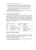
Table 6.1-1 applies with activation (start or switchover) of zone pairs 1 to 4.
Table 6.1-1:
Connection of control inputs FP1 to FP4 with activation of zone pairs 1
to 4
The following points also apply for the switchover:
•
The second zone pair must always be switched off first, then the first zone pair.
•
The switchover must be made within 1 sec. Both zone pairs are monitored during
the switchover time.
•
The switching process may not include the deactivation of all zone pairs at any
time.
•
The switchover process executed by the control unit must concur with the laser
scanner's configuration, which was set beforehand with SIMATIC FS600
Parameterization Software LS4soft.
If these points are not observed the laser scanner will fail within 40 ms and will show this
with the additional 2 Hz flashing of the green LED 1.
Table 6.1-2 applies with activation (start or switchover) of zone pairs 1 to 8.
Table 6.1-2:
Connection of control inputs FP1 to FP4 with activation of zone pairs 1
to 8
Zone pair
Control input
FP1-FP2-FP3-FP4
1
1 - 0 - 0 - 0
Zone pair 1 is active
2
0 - 1 - 0 - 0
Zone pair 2 is active
3
0 - 0 - 1 - 0
Zone pair 3 is active
4
0 - 0 - 0 - 1
Zone pair 4 is active
Zone pair
Control input
FP1-FP2-FP3-FP4
1
1 - 0 - 0 - 0
Zone pair 1 is active
2
0 - 1 - 0 - 0
Zone pair 2 is active
3
0 - 0 - 1 - 0
Zone pair 3 is active
4
0 - 0 - 0 - 1
Zone pair 4 is active
5
1 - 1 - 1 - 0
Zone pair 5 is active
6
1 - 1 - 0 - 1
Zone pair 6 is active
7
1 - 0 - 1 - 1
Zone pair 7 is active
8
0 - 1 - 1 - 1
Zone pair 8 is active
Summary of Contents for SIMATIC FS600
Page 2: ...600672 ...
Page 109: ...109 ...


