background image


IRD400 

40 

Operating Instructions, 05/2018, A5E36790512-AC 


Maintenance and repairs 


Maintenance 

The display unit is maintenance-free. Cyclic maintenance work is not required. However, you 

should still clean the device.  
Clean the front of the device if soiled, or if legibility of the LED display is impaired. 


NOTICE 
Risk of damage to the device 
Using compressed air, a steam cleaner, or aggressive solvents or scouring agents will 

damage the device. 
Use a cleaning cloth that is moistened with a cleaning agent to clean the equipment. Only 

use water with a little liquid soap or a screen cleaning foam. 


Repairs 

The display unit will not be repaired. You can send a defective device to the Retouren-

Center Fürth for error analysis . 
The address is: 
Siemens AG 

Division Digital Factory 

Retouren-Center 

Siemensstr. 2 

90766 Fürth 

Germany  
You will receive a credit note for the return device. A credit not is only granted if the party 

that submitted the device has ordered a new device. 

6.1


Recycling and disposal 

Recycling and disposal  

The products described in this manual can be recycled due to their low level of 

contaminants. Contact a certified disposal service company for environmentally sound 

recycling and disposal of your old devices. 


Summary of Contents for SIMATIC HMI IRD400

Page 1: ..._______ ___________________ ___________________ SIMATIC HMI HMI device IRD400 Operating Instructions 05 2018 A5E36790512 AC Preface Overview 1 Safety instructions 2 Installing and connecting the display unit 3 Operating the display unit 4 Configuring the display unit 5 Maintenance and repairs 6 Technical specifications 7 Appendix A ...

Page 2: ...ly by personnel qualified for the specific task in accordance with the relevant documentation in particular its warning notices and safety instructions Qualified personnel are those who based on their training and experience are capable of identifying risks and avoiding potential hazards when working with these products systems Proper use of Siemens products Note the following WARNING Siemens prod...

Page 3: ... are also going to need this document whenever the system is recommissioned Keep this and supplementary documentation in a safe place for the entire life cycle of the device Submit all of these documents to a future owner of the device Knowledge required General knowledge in the fields of electrical engineering automation technology and process communication is prerequisite for comprehension of th...

Page 4: ...ling or a specific section of the document to which you should pay particular attention Naming conventions Term Applies to Display unit SIMATIC HMI IRD400 Device Display unit Control cabinet Installation cabinet Enclosure Terminal box Console Switchboard Figures This document contains illustrations of the described devices The illustrations may deviate from the particularities of the delivered dev...

Page 5: ...unit 18 3 3 Connecting the display unit 19 3 3 1 Connection information 19 3 3 2 Connecting functional ground 20 3 3 3 Connecting the Power Supply 22 3 3 4 Connecting the PLC 24 3 3 5 Connecting digital inputs outputs 25 3 3 6 Securing the cables 25 4 Operating the display unit 26 5 Configuring the display unit 29 5 1 PROFINET modules 29 5 2 Configuring in the TIA Portal 30 5 3 Slot 1 IR RC module...

Page 6: ...4 Ambient conditions 44 7 4 1 Transportation and storage requirements 44 7 4 2 Operational requirements 45 7 4 3 Tests for ambient conditions 46 7 5 Dimensional diagram 47 7 6 Technical specifications 47 7 7 Interface description 49 7 7 1 Power supply 49 7 7 2 RS 232 interface X30 49 7 7 3 PROFINET 50 7 7 4 Digital inputs outputs 50 A Appendix 51 A 1 Technical support 51 A 2 Abbreviations 52 Index...

Page 7: ...conditions The display unit has an infrared transmitter receiver module which is tuned to the IR remote control with the article number 6ES7292 0CA50 0AA0 and can communicate with a display unit of the same design The display unit can be used with and without remote control You can use the IR remote control to adjust the brightness of the display on the display unit and transmit signals to the con...

Page 8: ...X1 P2 Recesses for a mounting clip Power supply connector X80 Green and red LEDs for example for displaying the operating state Mounting seal IR transmitter receiver module with blue LED I O interface X10 digital inputs outputs Rating plate Display with three 7 segment displays Connection for functional earthing The RS 232 interface X30 is deactivated ...

Page 9: ...uts The display unit communicates with the controller via PROFINET The response of the digital inputs outputs pins 1 8 of the I O interface X10 is defined via the configuration of the slots in HW Config TIA Portal and is freely programmable 1 4 Accessories Accessories for the display unit IR remote control The IR remote control represents the input device for the display unit The article number is...

Page 10: ... Safety during commissioning and operation WARNING Installation use as intended It is strictly forbidden to commission the device before compliance with Machinery Directive 2006 42 E has been verified for the machine to be operated with this device Verify before commissioning that the provisions of Directive 2006 42 EC are fulfilled Safety when working in and on electrical systems Only authorized ...

Page 11: ...sent to the controller Unintentional reaction of the plant as well as personal injury or property damage can result Note Do not operate any infrared signal sources except the permitted remote control in the entire receiving range of the display unit Only the remote control IR RC with article number 6ES7292 0CA50 0AA0 is permitted Take appropriate measures to prevent interference by other sources w...

Page 12: ...al security concept Siemens products and solutions only form one element of such a concept Siemens products and solutions only form one element of such a concept Customer is responsible to prevent unauthorized access to its plants systems machines and networks Systems machines and components should only be connected to the enterprise network or the internet if and to the extent necessary and with ...

Page 13: ...or visible signs of transport damage and for completeness Note Damaged parts Do not install parts damaged during shipment In the case of damaged parts contact your Siemens representative The package content is described in section Scope of delivery Page 7 Keep the provided documentation in a safe place The documentation is part of the HMI device and is required for subsequent commissioning ...

Page 14: ...al installation angles are permitted Mounting position Deviation from the perpendicular axis Temperature Horizontal 90 0 50 C Inclined 35 0 60 C Vertical 0 0 60 C Inclined 35 0 60 C The display unit is quipped with venting slots for heat convection into the control cabinet where thermal energy is dissipated on the panels of the control cabinet Note You risk damage to the display unit if operating ...

Page 15: ...rmitted tilt of the front of the device must be taken into consideration The following angles of inclination are permitted for a short time for the display unit during movement Position Deviation from the perpendicular axis Tilted 35 Vertical 0 Tilted 35 Inclinations may occur for example if the display unit is mounted to a conveying device that services several levels of the plant Note Please not...

Page 16: ...ion may lead to malfunctions Observe the permissible ambient conditions when selecting the installation location When selecting the mounting location for the display unit ensure that sufficient heat convection is possible Avoid installation of heat generating equipment directly underneath the display unit Clearance The following clearance is required for ventilation of the display unit 10 mm clear...

Page 17: ...e following conditions must be met to ensure the degree of protection The material at the mounting cut out must be resistant to distortion Material thickness at the mounting cut out for IP65 degree of protection or for enclosure type 4X type 12 indoor use only 2 mm bis 6 mm Permitted deviation from plane at the mounting cutout 0 5 mm This condition must be fulfilled for the mounted HMI device Perm...

Page 18: ...t 4 mounting clips 4 threaded pins for the mounting clips Procedure Note Secure mounting clips You will risk damage to the enclosure of device if you continue to turn the mounting screw while the gap between the device and the panel of the control cabinet is already closed Once the gap is closed do not turn the mounting screw any further You have the option to tighten the mounting clamp with a tor...

Page 19: ...is to be installed 3 Screw in the threaded pin until the gap between the enclosure front and the display unit is closed Degree of protection IP65 achieved when the gap is closed 3 3 Connecting the display unit 3 3 1 Connection information Wiring sequence Note You will risk damage to the device if you ignore the specified wiring sequence Wire the device in the following sequence 1 Functional ground...

Page 20: ... dried completely before switching it on Wiring cables Make sure that you do not bend the pins when connecting the cables Note You will risk malfunctions if using cables that are not approved Always use shielded standard cables for data transmission Orders for accessories can be placed at the following Internet URL Industry Mall https mall industry siemens com 3 3 2 Connecting functional ground Po...

Page 21: ... In practical life equipotential bonding conductors with a minimum cross section of 16 mm are generally accepted for the interconnection between control cabinets or with grounding busbars Use equipotential bonding conductors made of copper or galvanized steel Interconnect the equipotential bonding conductors and the earth rod protective conductor on a large surface and protect these against corros...

Page 22: ...power supply units with safe electrical isolation in accordance with IEC 60364 4 41 or HD 384 04 41 VDE 0100 Part 410 for example in accordance with the PELV standard The supply voltage must be within the specified voltage range Incorrect voltage may cause function failures on the device Applies to non isolated system design Note Connect the GND 24 V connection from the 24 VDC power supply output ...

Page 23: ...rules are not required NOTICE Wire mains terminal outside the device Do not tighten the screws of the main terminal block while it is inserted in the device The pressure of the screwdriver on the power supply terminal and the socket can damage the device Only connect the cables to the mains terminal when it is not plugged in Connect the power supply lines to the mains terminal according to the fol...

Page 24: ...oved cables to connect a SIMATIC S7 controller Standard cables are available for the connection You can find ordering information on the Internet https mall industry siemens com Connection diagram You can find additional information on the topology of PROFINET networks in the following manual SIMATIC PROFINET system description https support industry siemens com cs us en view 19292127 ...

Page 25: ...h regard to stripping insulation Note Risk of damage to the device Do not connect the cables if the plug in connector is plugged into the HMI device You may damage the fastening of the connector in the device Only connect cables when the connectors are unplugged To open the plug in connectors press in the opening provided using a screwdriver for slotted screws Push the cable into the housing of th...

Page 26: ...iving remote control signals Operating mode IR P2P Communication with a different display unit of the same type It is not possible to enter control commands directly at the display unit For information about the remote control refer to section Accessories Page 9 Infrared transmitter receiver module of the display unit The transmitter receiver module of the display unit operates in the infrared ran...

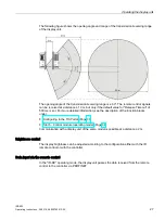
Page 27: ... of 500 ms is set For more detailed information see the description of the function blocks under Configuring in the TIA Portal Page 30 Slot 5 Control module operating mode Page 38 Communication with a display unit of the same model is possible at a distance 2 m Brightness control The display brightness can be adjusted according to the configuration either with the IR remote control or with the con...

Page 28: ...d Note Throughout the entire duration of the data transmission the transmission and reception range of the two display units must overlap During data transmission the two display units must face each other and be still During the period of data transmission the remote control may not be used The maximum data rate for the data transmission is 1333 bps A data packet contains 16 bytes of user data Ad...

Page 29: ...values in the GSDML file or set using HW Config in the TIA Portal This parameter is only transmitted while PROFINET communication is being established The addressing of record data is defined by the lower slot ID in the engineering program and the RecordDataItem index in the GSDML file Communication is based on acyclic PROFINET read write services readRec IN No Acyclic PROFINET read services are g...

Page 30: ...e the PROFINET interfaces of each PROFINET module The GSDML file is also structured based on this description The GSDML file contains additional details for example IO addresses 5 2 Configuring in the TIA Portal The following section briefly describes the configuration in TIA Portal You find the device in the hardware catalog in the following path ...

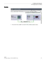
Page 31: ...figuring the display unit 5 2 Configuring in the TIA Portal IRD400 Operating Instructions 05 2018 A5E36790512 AC 31 Procedure 1 In the network view establish a connection to the controller see figure above ...

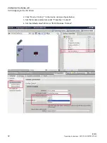
Page 32: ...g in the TIA Portal IRD400 32 Operating Instructions 05 2018 A5E36790512 AC 2 Click Device Control_1 in the device view see figure below 3 Set the module parameters under Properties General 4 Set the default value 500 ms as IR RC Release Timeout ...

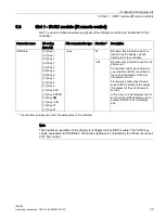
Page 33: ... key information which is received by the display unit and transferred to the controller OUT Bit coded key information sent by the display unit Transmission starts when data val ues other than ZERO are written to the output Q address of the slot IR remote control Transmission ends when the data value ZERO is written to the output Q address of the slot IR remote control In this way a 2 byte telegra...

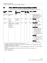
Page 34: ... 4 7 Brightness recordData writeRec 2 OUT Byte 1 0x80 Disp_ON_OFF 0 Switch off the display 1 Switching on the display Blue_LED_Ctrl 0 Blue LED blinks when signals are received by the remote control in operating mode IR RC 1 The controller deter mines the behavior of the blue LED Bright_Ctrl 0 Brightness is controlled by the remote control 1 Brightness is controlled by the controller Brightness 0 7...

Page 35: ... 0x6D 5 0 1 1 1 1 1 0 1 0x7D 6 0 0 0 0 0 1 1 1 0x07 7 0 1 1 1 1 1 1 1 0x7F 8 0 1 1 0 1 1 1 1 0x6F 9 0 1 1 1 1 0 0 1 0x79 E 0 1 1 1 0 0 0 1 0x71 F 0 1 0 1 1 1 0 0 0x5C o 0 1 1 1 0 0 1 1 0x73 P 0 1 0 1 0 0 0 0 0x50 r 0 1 0 0 0 0 0 0 0x40 1 0 1 1 1 1 1 1 0xBF 0 1 0 0 0 0 1 1 0 0x86 1 1 1 0 1 1 0 1 1 0xDB 2 1 1 0 0 1 1 1 1 0xCF 3 1 1 1 0 0 1 1 0 0xE6 4 1 1 1 0 1 1 0 1 0xED 5 1 1 1 1 1 1 0 1 0xFD 6 1 0...

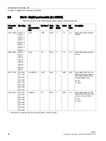
Page 36: ...ed status of digital outputs DIOC_datI 0 DI 0 1 DI 1 2 DI 2 3 DI 3 4 DI 4 5 DI 5 6 DI 6 7 DI 7 cyclic IN Byte 1 n a n a Bit coded status of digital inputs DIOC_conf 0 conf 0 1 conf 1 2 conf 2 3 conf 3 4 conf 4 5 conf 5 6 conf 6 7 conf 7 recordData OUT Byte 1 0x80 0x00 Bit coded direction of the digital inputs outputs sent from the controller during the PROFINET start 0 IN 1 OUT DIOC_stat 0 conf 0 ...

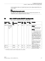
Page 37: ...it value Description IRPP_stat 0 TX Busy 1 RX Busy 2 7 not used cyclic IN Byte 1 n a n a IR P2P status TX Busy 0b Sending data inactive 1b Sending data active RX Busy 0b Receiving data inactive 1b Receiving data active Details for RX Busy If a cor rect start byte is received the flag RX Busy is set for 10 ms Each additional byte received within 10 ms sets the flag RX Busy for an additional 10 ms I...

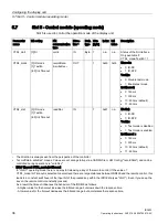
Page 38: ...d 1 Test mode is enabled IrrcTimeout 3 0 150 ms 1 300 ms 10 500 ms default 11 800 ms 1 The direction is always seen from the perspective of the controller 2 recordData writeRec means Values are set during startup via a GSDML file or HW Config recordData and can be controlled during operation via writeRec 3 IRRC Timeout CTRL_mode IrrcTimeout In IR RC operating mode there is a delay for releasing a ...

Page 39: ...he controller about the current status using the CTRL_stat signal to enable the control program to respond to the status of the display unit WARNING Only enable test mode for test purposes In test mode functions are enabled which may not be used during operation This can result in personal injury or property damage Operate the device only with debug mode disabled setting CTRL_mode TestEn 0 See als...

Page 40: ... the equipment Only use water with a little liquid soap or a screen cleaning foam Repairs The display unit will not be repaired You can send a defective device to the Retouren Center Fürth for error analysis The address is Siemens AG Division Digital Factory Retouren Center Siemensstr 2 90766 Fürth Germany You will receive a credit note for the return device A credit not is only granted if the par...

Page 41: ...s for programmable logic controllers which were published in the Official Journals of the European Union 2014 30 EU Electromagnetic Compatibility Directive EMC Directive EU Declaration of Conformity The EU Declarations of Conformity are available to the relevant authorities at the following address Siemens AG Digital Factory Factory Automation DF FA SE Breslauer Str 5 D 90766 Fürth UL approval Und...

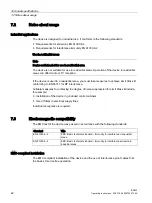
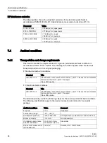
Page 42: ...st take measures to achieve Limit Class B conforming to EN 55011 for RF interference Suitable measures for achieving the degree of noise suppression for Limit Class B include for example Installation of the device in grounded control cabinets Use of filters in electrical supply lines Individual acceptance is required 7 3 Electromagnetic compatibility The EMC test of the device was passed in accord...

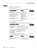
Page 43: ...on elements 3 1 For 24 V DC voltage only with protection element Sinusoidal disturbance The following table shows the EMC of the device in terms of sinusoidal disturbance Sinusoidal disturbance Test value Corresponds to degree of severity HF radiation in elec tromagnetic fields in accordance with IEC 61000 4 3 80 amplitude modulation at 1 kHz Up to 10 V m in the 80 MHz to 1000 MHz range Up to 10 V...

Page 44: ...l packaging Mechanical ambient conditions Standard Title IEC 60721 3 2 Classification of environmental conditions part 3 Classes of environmental factors and their limits part 2 Transport Class 2M2 applies Climatic ambient conditions Standard Title IEC 60721 3 2 Classification of environmental conditions part 3 Classes of environmental factors and their limits part 2 Transport Class 2K4 applies Th...

Page 45: ...e most important ambient conditions Ambient conditions Value Comments Temperature range 0 to 60 C Humidity 95 no condensation Atmospheric pressure 1140 to 795 hPa Corresponds to an altitude of 1000 to 2500 m Operation with additional protective measures You must take additional measures to operate the HMI device at the following locations At locations with a high degree of ionizing radiation At lo...

Page 46: ...g operation Test Physical variable Value comment Vibrations in accordance with IEC 60068 2 6 test Fc Vibration 1 octave min 10 cycles per axis Frequency range 5 to 8 4 Hz deflection 3 5 mm 8 4 to 200 Hz vibration acceleration 9 8 m s2 Shock in accordance with IEC 60068 2 27 test Ea Shock form Half wave sine Acceleration 15 g Duration 11 ms Number of shocks 3 per axis Repetitive shock in accordance...

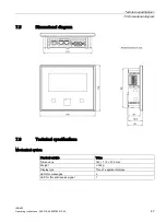
Page 47: ...g Instructions 05 2018 A5E36790512 AC 47 7 5 Dimensional diagram 7 6 Technical specifications Mechanical system Physical variable Value Dimensions 140 116 37 5 mm Weight 380 g Display type Three 7 segment displays LEDs for messages 2 LED for IR send receive signal 1 ...

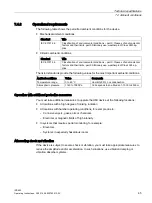
Page 48: ...voltage Ue relative to other circuits or ground 50 V 500 V DC Ethernet connector 1500 VAC 1 with max loaded digital outputs Interfaces Interface Value PROFINET LAN X1 2 x RJ45 10 100 Mbps RS 232 X30 not used Digital inputs outputs Physical variable Value Permissible control elements at the interface Keys switches Number of digital inputs outputs 8 Electrically isolated from internal logic No Cable...

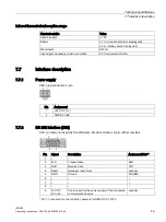
Page 49: ...e control 7 7 Interface description 7 7 1 Power supply X80 plug connector 2 pin Pin Assignment 1 24 V DC L 2 GND 24 V M 7 7 2 RS 232 interface X30 X30 currently not used by the software D sub connector 9 pin with screw lock Pin Signal Description Assignment PLC 1 2 TxD Transmit data RxD 3 RxD Receive data TxD 4 Reset Hardware reset input optional 5 GND Ground M GND 6 7 8 9 5 VDC 200 mA Can be used...

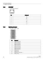
Page 50: ...Rx 4 n c 5 n c 6 Rx 7 n c 8 n c 7 7 4 Digital inputs outputs X10 plug connector 12 pin Pin Assignment 1 digital input output 0 2 digital input output 1 3 digital input output 2 4 digital input output 3 5 digital input output 4 6 digital input output 5 7 digital input output 6 8 digital input output 7 9 GND ground 10 GND ground 11 Digital input for test mode 12 GND ground ...

Page 51: ...om automation support request Service http support automation siemens com WW view en 16604318 Contacts and office locations http www automation siemens com mcms aspa db en Pages default aspx Training center http sitrain automation siemens com sitrainworld AppLang en SIMATIC product information is available at Industry Portal http www automation siemens com _en portal index htm Overall SIMATIC docu...

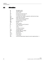
Page 52: ...tic discharge EMS Electrical Monorail System EMS400S Electric Monorail System 400 Signal EMC Electromagnetic compatibility EN European standard GND Ground HF High Frequency IEC International Electronic Commission IP Ingress Protection IR Infrared IT Information Technology LED Light Emitting Diode PELV Protective Extra Low Voltage PI Product information RxD Receive Data Sub D Subminiature D TxD Tra...

Page 53: ...rmity 41 Device failure 20 Digital inputs outputs Technical specifications 48 Display unit Clearance 16 Installation location 16 Mounting 18 Mounting position 14 Disposal 40 Document SIMATIC complete 51 E EC Declaration of Conformity 41 Electrical system Technical specifications 48 Emission 42 ESD 12 I Industry Portal 51 Infrared transmission reception range Technical specifications 49 Infrared tr...

Page 54: ... 11 Radio interference 42 Rating plate 41 Receiver module 26 Recycling 40 RS 232 Technical specifications 48 S Scope Operating instructions 3 Scope of delivery 7 Service 51 Support Technical 51 Support request 51 T Technical specifications 47 Technical support 51 Technical Support 51 Training center 51 Transmitter module 26 U Use In residential areas 42 Industrial 42 W Wiring Cable 20 Sequence 19 ...

Reviews: