background image


Technical specifications 


7.5 Hardware descriptions 

SIMATIC IPC527G 
Operating Instructions, 03/2019, A5E45491226-AA 

69


7.5.2.3


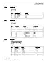
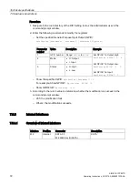
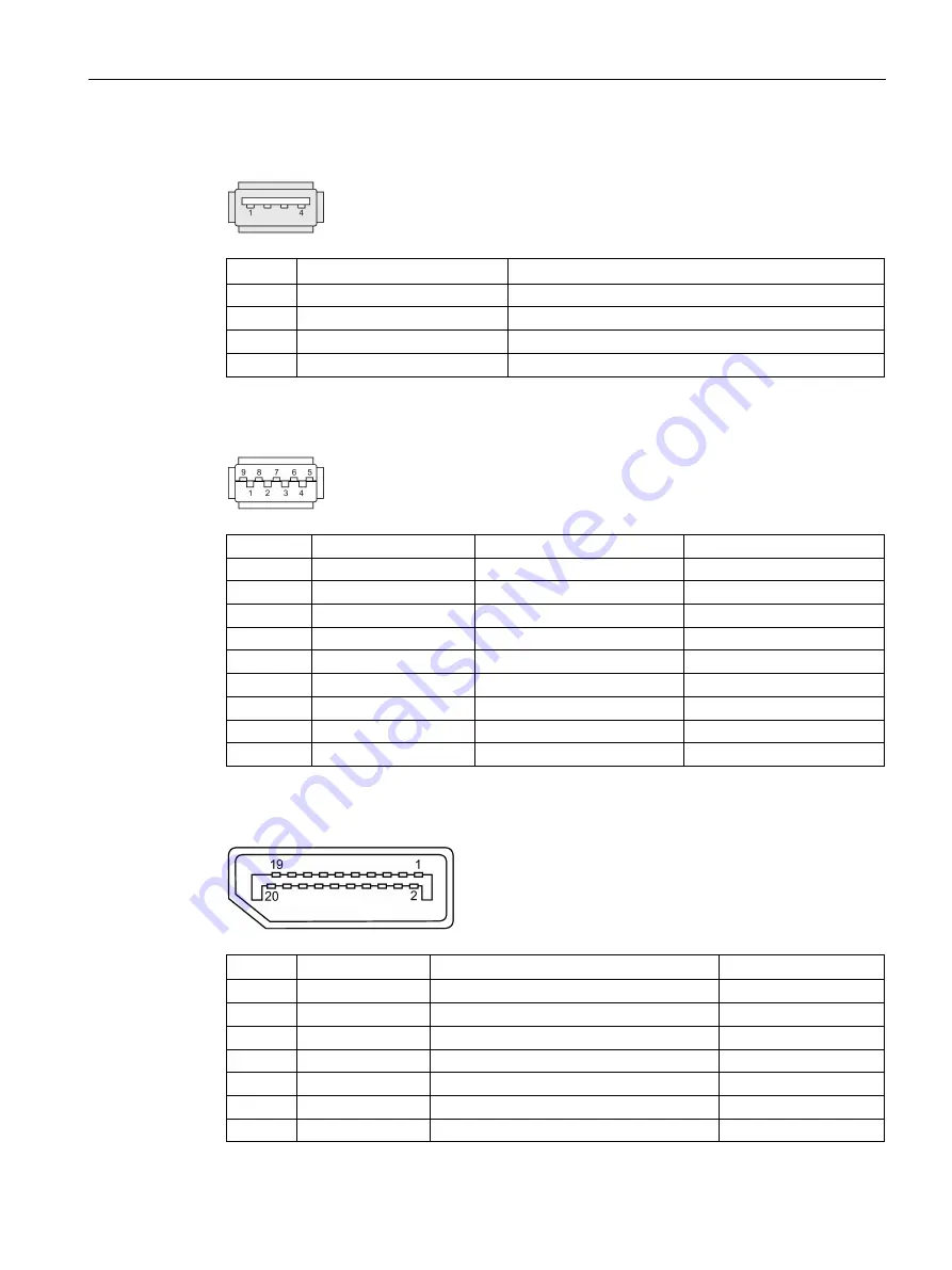
USB 2.0 port 


Pin 

Short description 

Meaning 

USB_P5V_fused (O) 

+5 V, fused 

USB_D0M (I/O) 

Data– 

USB_D0P (I/O) 

Data+  

USB_GND 

GND  

7.5.2.4


USB 3.0 port 


Pin 

Short name 

Meaning 

Input / output 

VBUS 

+ 5 V (fused) 

Output 

D- 

Data channel USB2 

Input / output 

D+ 

Data channel USB2 

Input / output 

GND 

Ground 

–  

RX- 

Data channel USB3 

Input 

RX+ 

Data channel USB3 

Input 

GND 

Ground 

–  

TX- 

Data channel USB3 

Output 

TX+ 

Data channel USB3 

Output 

7.5.2.5


DisplayPort 


Pin 

Short name 

Meaning 

Input / output 

DP data 0+ 

Output 

GND 

Ground  

-  

ML_Lane0- 

DP data 0- 

Output 

DP data 1+ 

Output 

GND 

Ground 

ML_Lane1- 

DP data 1- 

Output 

DP data 2+ 

Output 
Summary of Contents for Simatic IPC527G

Page 1: ...verview 1 Safety instructions 2 Installing and connecting the device 3 Commissioning the device and device functions 4 Expanding and assigning parameters to the device 5 Maintaining and repairing the device 6 Technical specifications 7 Appendix Motherboard A Technical support B Markings and symbols C List of abbreviations D ...

Page 2: ...ly by personnel qualified for the specific task in accordance with the relevant documentation in particular its warning notices and safety instructions Qualified personnel are those who based on their training and experience are capable of identifying risks and avoiding potential hazards when working with these products systems Proper use of Siemens products Note the following WARNING Siemens prod...

Page 3: ... knowledge in the field automation control engineering is recommended Validity of the operating instructions These operating instructions are valid for all versions of the SIMATIC IPC527G Scope of this documentation The documentation for the SIMATIC IPC527G consists of Quick Install Guide SIMATIC IPC527G SIMATIC IPC527G Operating Instructions in English and Chinese The PDF version of the documenta...

Page 4: ... 1 Checking the delivery package 17 3 1 2 Identification data of the device 18 3 1 3 Permitted mounting positions 20 3 2 Mounting the device 21 3 2 1 Mounting instructions 21 3 2 2 Desk mounting 23 3 2 3 Wall mounting 23 3 2 4 Book mounting 25 3 2 5 Tower mounting 26 3 3 Connecting the device 27 3 3 1 Notes on connecting 27 3 3 2 Connecting the function earth 27 3 3 3 Connecting the power supply 2...

Page 5: ...esidential Areas 58 7 2 2 ESD guideline 58 7 3 Dimension drawings 60 7 4 Technical data 62 7 4 1 General technical specifications 62 7 4 2 Environmental conditions 65 7 4 3 Power demand of the components 66 7 4 4 Basic power supply 66 7 5 Hardware descriptions 67 7 5 1 Technical features of the motherboard 67 7 5 2 External interfaces 67 7 5 2 1 Overview of interfaces 67 7 5 2 2 Serial interface 6...

Page 6: ...X12V ATX_PWR 98 A 2 4 Digital I O connector DIO 99 A 2 5 Serial port connectors COM3 COM4 100 A 2 6 M 2 B Key slot 101 A 2 7 USB 2 0 connectors USB56 USB78 USB9 102 A 2 8 System panel connector F_PANEL 103 B Technical support 104 B 1 Service and support 104 B 2 Troubleshooting 105 B 3 Notes on the use of third party modules 106 C Markings and symbols 107 C 1 Overview 107 C 2 Safety 107 C 3 Operato...

Page 7: ...ng Instructions 03 2019 A5E45491226 AA 7 Overview 1 1 1 Product description SIMATIC IPC527G is a compact PC with industrial functionality Compact design Expandability expansion card slots Scalability Rugged Various interfaces ...

Page 8: ...e 16 slot 1 PCIe 16 slot 1 PCIe 1 slot 2 PCI slot with riser card Graphics Integrated Graphic Controller 1 VGA DB 15 1 DP DDI VGA support max to 1920 1200 pixels DP support max to 4K Power supply 100 V AC to 240 V AC 10 10 Drives and storage media Hard Disk Drive HDD optional 1 TB 2 5 HDD SATA Solid State Drive SSD optional 128 GB 2 5 SSD SATA 256 GB 2 5 SSD SATA 512 GB 2 5 SSD SATA M 2 Solid Stat...

Page 9: ...nd Output 5V 12mA Keyboard mouse Connection through USB port Operating systems Operation Systems Without Windows 7 Ultimate 32 bit MUI SP1 1 Windows 7 Ultimate 64 bit MUI SP1 1 1 MUI Multi language user interface More language packages are available on the USB stick You can install them according to your request The configurations are not released in the current version For the detailed configurat...

Page 10: ...f the devices SIMATIC IPC527G 10 Operating Instructions 03 2019 A5E45491226 AA 1 2 Structure of the devices 1 2 1 Views of the basic device Front view The following picture shows the front view of IPC527G Function earth Ports ...

Page 11: ...Overview 1 2 Structure of the devices SIMATIC IPC527G Operating Instructions 03 2019 A5E45491226 AA 11 Rear view Mounting bracket Air inlet 1 2 2 Interfaces of the basic device ...

Page 12: ...ophone port pink X91 Connection for microphone 4 USB X60 X61 X62 X63 USB 3 1 Gen 1 up to 5Gbps ports 2 Ethernet X1P1 X2P1 RJ45 Ethernet connection for 10 100 1000 Mbps DPP X71 DisplayPort connection for digital monitor VGA X70 Connection for monitor with Video Graphics Adapter VGA interface COM1 2 X30 X31 Serial interface 9 pin RS232 RS422 RS485 Function earth Connection for function earth 1 2 3 S...

Page 13: ...at can be implemented please visit https www siemens com industrialsecurity Siemens products and solutions undergo continuous development to make them more secure Siemens strongly recommends that product updates are applied as soon as they are available and that the latest product versions are used Use of product versions that are no longer supported and failure to apply the latest updates may inc...

Page 14: ...e device machine or plant Device and system expansions may violate safety rules and regulations regarding radio interference suppression If you install or exchange system expansions and damage your device the warranty becomes void Note the following for system expansions Only install system expansion devices designed for this device Contact your technical support team or where you purchased your P...

Page 15: ...s Replace used batteries in good time see the section Replacing the backup battery Page 48 in the operating instructions Replace the lithium battery only with the type recommended by the manufacturer type CR2032 For any requirements on product maintenance contact Siemens Technical support Page 104 Do not throw lithium batteries into fire do not solder on the cell body do not recharge do not open d...

Page 16: ... components that can be destroyed by electrostatic discharge observe the ESD Guideline Page 58 2 4 Notes on use NOTICE Possible functional restrictions in case of non validated plant operation The device is tested and certified on the basis of the technical standards In rare cases functional restrictions can occur during plant operation Validate the correct functioning of the plant to avoid functi...

Page 17: ...iately 3 Unpack the device at its installation location 4 Keep the original packaging in case you have to transport the unit again 5 Check the contents of the packaging and any accessories you ordered for completeness and damage Note Damage to the device during transport and storage If a device is transported or stored without packaging shocks vibrations pressure and moisture may impact the unprot...

Page 18: ... weather moisture could build up on or inside the device Moisture causes a short circuit in electrical circuits and damages the device In order to prevent damage to the device proceed as follows Store the device in a dry place Bring the device to room temperature before starting it up Do not expose the device to direct heat radiation from a heating device If condensation develops wait approximatel...

Page 19: ...AC Ethernet address 3 MAC Optional Product label The following image shows the product label on the SIMATIC IPC527G as an example Note Replacement device without storage media When you order a replacement device remove all the storage media from your device for example HDD Insert the storage media into the replacement device COA label Microsoft Windows Product Key on the Certificate Of Authenticit...

Page 20: ... General technical specifications Page 62 If the device has been fitted with expansion cards please observe the safety and installation instructions for the expansion cards in the corresponding documentation If in doubt install the device in an enclosure that is compliant with IEC UL EN DIN EN 60950 1 sections 4 6 and 4 7 3 Note The device is approved for indoor operation only Ensure that the requ...

Page 21: ...If the equipment is used in a manner not specified by the manufacture the protection provided by the equipment might be impaired Note the following The device is approved for indoor operation only When the device is used in the area of Industrial Control Equipment in accordance with UL61010 2 201 the device is classified as Open equipment Open equipment must be installed within an enclosure which ...

Page 22: ...otal weight of the device including fixing elements NOTICE Incorrect fixing elements If you use anchors and screws other than those specified below for wall and vertical mounting safe mounting is not guaranteed The device can fall and may be damaged Use only the anchors and screws specified in the following table Use the following fasteners for the permitted mounting positions Material Hole diamet...

Page 23: ...ews for mounting to a horizontal shelf Procedure for mounting Secure each mounting bracket with 3 M3 screws to the device The maximum penetration depth is 5 mm Use the marked threaded holes 3 2 3 Wall mounting Wall mounting is one of the vertical mounting types Requirement Two mounting brackets A T10 screwdriver 6 M3 screws from deliver package Another four screws for mounting to the wall Procedur...

Page 24: ...evice 3 2 Mounting the device SIMATIC IPC527G 24 Operating Instructions 03 2019 A5E45491226 AA Use the marked threaded holes The wall mounting has two mounting positions The interfaces are at the left The interfaces are at the right ...

Page 25: ...unting to the wall Procedure for mounting Secure each mounting bracket with 3 M3 screws to the device The maximum penetration depth is 5 mm Use the marked threaded holes The book mounting has two mounting positions The interfaces are at the front Mount the device as the following image Note In order to reserve some space for the ventilation select the slot near the outside to secure the screw The ...

Page 26: ...f the vertical mounting types and it is a space saving installation of the device Requirement Two mounting brackets A T10 screwdriver 6 M3 screws from deliver package Another four screws for mounting to a horizontal shelf Procedure for mounting Secure each mounting bracket with 3 M3 screws to the device The maximum penetration depth is 5 mm Use the marked threaded holes ...

Page 27: ...e Use a central power isolating switch for cabinet installation WARNING Risk of lightning strikes A lightning flash may enter the mains cables and data transmission cables and jump to a person Death serious injury and burns can be caused by lightning Take the following precautions Disconnect the device from the power supply in good time when a thunderstorm is approaching Do not touch mains cables ...

Page 28: ...e connected to the function earth of the control cabinet or system in which the device is installed Never operate the device without function earth If a device is defective remove it from operation without delay and label it accordingly Requirement T20 screwdriver Cable lug for M4 Function earth with minimum cross section of 2 5 mm2 copper cable Procedure Clamp the cable lug on the function earth ...

Page 29: ...s IT networks Operate the device only in grounded power networks TN networks in accordance with IEC 60364 1 Country specific information The power supply cable must conform to the safety regulations of the country in which the devices are installed and bear the marks required in each case This device must be equipped with a safety tested power cord which may only be connected to a grounded shockpr...

Page 30: ... V supply voltage Type SJT with three conductors Conductor cross section 18 AWG Cable length 4 5 m 220V supply voltage Type RVV with three conductors conductor cross section 18 AWG Cable length 4 5 m Connecting the power supply Connect the power cable to socket Insert the power cable in the electrical socket Press the power button ...

Page 31: ...sh a network between the device and other computers via Industrial Ethernet The on board LAN interfaces are twisted pair TP interfaces that support data transmission rates of 10 100 1000 Mbps Note You need a category 6 Ethernet cable for operation at 1000 Mbps PROFINET PROFINET can be operated via Standard Ethernet interfaces RT SIMATIC NET Use this software package to create operate and configure...

Page 32: ...tem For the configurations without operating system pre installed contact the operating system provider to install the operating system firstly NOTICE Faulty installation If you change the default values in the BIOS setup or if you turn off the device during the installation you disrupt the installation and the operating system is not installed correctly The operating safety of the device and the ...

Page 33: ...oftware Page 51 Note Once the operating system has been set up the device will restart Result The interface of the operating system is displayed every time you turn on the device and after the startup routine 4 3 Switching off the device Shutting down the operating system For Windows operating systems Select Start Shut down or Briefly press the on off switch unless otherwise configured in the powe...

Page 34: ...ime If the device was not mounted in a control cabinet Shut down the operating system and pull the power plug on the rear of the device If the device was mounted in a control cabinet Shut down the operating system and switch the AC circuit breaker to Off The device is switched off and fully disconnected from the mains voltage No trickle current is flowing Hardware reset You can perform a hardware ...

Page 35: ...sers Windows checks if the device is protected by a software firewall The firewall is enabled by default in the delivery state Antivirus software Antivirus programs add protection to the device by searching for and eliminating viruses and other security threats Windows checks if a full range up to date antivirus program is running on the device No antivirus software is installed in the delivery st...

Page 36: ...e following precautions Always disconnect the power plug before you open the device Close the device after every repair CAUTION Electrostatic sensitive devices ESD The device contains electronic components which are destroyed by electrostatic charges This can result in malfunctions and damage to the machine or plant Make sure that you take precautionary measures before you open the device Requirem...

Page 37: ...device SIMATIC IPC527G Operating Instructions 03 2019 A5E45491226 AA 37 Procedure opening the device Loose the marked retaining screw Lift up the cover Procedure closing the device To close the device carry out the steps for opening the device in the reverse order ...

Page 38: ...lease note the following Observe the safety and installation instructions for the expansion cards If in doubt install the device in an enclosure that is compliant with requirements to sections 4 6 and 4 7 3 of the EN 60950 1 2006 and IEC UL EN DIN EN 60950 1 standards Expansion cards that comply with the following standards are supported PCI Rev 2 3 Expansion cards with 5 V supply voltage can be o...

Page 39: ...rocedure Installing the extension card Remove the marked retaining screws and remove the slot cover plate for the expansion card Insert the expansion card into the slot Secure the extension card with the screw you removed in step Procedure Removing the extension card Follow the above steps in reverse order to remove the extension card ...

Page 40: ...device is opened Disconnect all the cables on the motherboard A T10 screwdriver Procedure Installing the riser card Align the golden finger on the riser card with the PCIe x 4 slot on your motherboard and then press firmly until the riser card is completely seated on the slot Secure the riser card to the chassis with marked screws Procedure Removing the riser card Follow the above steps in reverse...

Page 41: ...Module Size Description DDR4 SDRAM 16GB DDR4 2048M 64 SODIMM 260pin DDR4 SDRAM 8GB DDR4 1024M 64 SODIMM 260pin DDR4 SDRAM 4GB DDR4 512M 64 SODIMM 260pin Requirement The device is disconnected from the power supply All connecting cables on the device are unplugged NOTICE Electrostatic discharge The electronic components on the PCBs are highly sensitive to electrostatic discharge Always take appropr...

Page 42: ...an be installed only when the direction is correct Switch the direction if the memory cannot able to be inserted into the memory socket DDR2 and DDR3 memory modules are not compatible Please make sure to install DDR4 Memory Module on this motherboard Follow the steps below to install memory module on motherboard memory sockets Press the retaining clips outward to unlock the memory socket Align a m...

Page 43: ...ive Read the information in section Repair information Page 45 The device provides two slots for disk drive you can install any of two disk drives in the drive bay Disk Drive Capacity range Type Hard Disk Drive HDD 500 GB to 2TB 2 2 5 HDD SATA Solid State Drive SSD 64 GB to 1TB 2 2 5 SSD SATA Requirement The device is open A PH2 screwdriver ...

Page 44: ...structions 03 2019 A5E45491226 AA Procedure Removing the disk drive Pull out the connection plug Lay down the device s rear panel including the drive Remove the indicated screws Take out the HDD or SSD Procedure Installing the disk drive Follow the steps in reverse order to install the disk drive ...

Page 45: ...ct the power plug before you open the device Only install system expansion devices designed for this device If you install other expansion devices you may damage the device or violate the safety requirements and regulations on RF suppression Contact your technical support team or where you purchased your PC to find out which system expansion devices may be installed If you install or exchange syst...

Page 46: ...on must be observed UL approval of the device only applies when the UL approved components are used according to their Conditions of Acceptability We are not liable for functional limitations caused by the use of third party devices or components Tools Tools to open the device see section Open the device Page 36 You can make repairs on the device with the following tools T20 screwdriver for functi...

Page 47: ...ing and removing hardware SIMATIC IPC527G Operating Instructions 03 2019 A5E45491226 AA 47 Procedure removing Remove the retaining screw Unscrew the marked screws on the enclosure Lift up the cover Pull out the fan plug Take the fan out of the device ...

Page 48: ... batteries also can result in an explosion of the batteries Explosion of the batteries and the released pollutants can cause severe physical injury Aged batteries jeopardize the function of the device Note the following when handling lithium batteries Replace the battery every 5 years Replace the lithium battery only with the type recommended by the manufacturer The new lithium battery must be cer...

Page 49: ...2032 Tension nominale 3 V CC Courant de charge anormal max 10 mA Pour toute demande concernant la maintenance du produit contactez le support technique Page 104 Siemens Ne jetez pas au feu des piles au lithium n effectuez pas de soudage sur la pile ne la rechargez pas ne l ouvrez pas ne la court circuitez pas n intervertissez pas les pôles ne la chauffez pas à plus de 100 C et protégez la de l ens...

Page 50: ...Installing and removing hardware SIMATIC IPC527G 50 Operating Instructions 03 2019 A5E45491226 AA Procedure Lay the cover on the desk Move the marked clip to one side and then take out the battery to replace with a new one Reset the BIOS setup ...

Page 51: ...ers list You need to install the following drivers on Windows 7 Operating system Drivers needed Windows 7 Step1 Intel R Chipset Device Software Step2 Microsoft Net Framework Step3 Intel R Management Engine Step4 Intel R USB3 0 3 1 eXtensible Host Controller Driver Step5 Intel AHCI Driver Step6 Intel R Network Connections Driver Step7 Intel R Graphics Driver Step8 Realtek High Decfinition Audio Dri...

Page 52: ... installation is completed Step 2 install the NetFX driver 1 Click Step2 Microsoft Net Framework 2 Click to install the NetFX driver 3 Click Yes to confirm the user account control question 4 Click Next to continue 5 Select the radio button before I have read and accept the license terms and click Install to allow the computer to start the installation 6 Click Finish The installation is completed ...

Page 53: ...ish The installation is completed Step 5 install the AHCI driver 1 Click Step5 Intel AHCI Driver 2 Click to install the AHCI driver 3 After you can see PASS in the command prompt window press any key to finish the installation Step 6 install the Network Connection driver 1 Click Step6 Intel R Network Connections Driver 2 Click to install the LAN driver 3 Click the Install Drivers and Software butt...

Page 54: ...irm the user account control question 4 Click Next to continue 5 Click Install to continue the installation 6 Select the radio button next to Yes I want to restart my computer now and click OK to restart the computer for the changes to take effect Step 9 install the SIO driver 1 Click Step9 Nuvoton SIO COMMPort Driver 2 Follow the prompt to install the Hotfix firstly and restart the computer 3 And...

Page 55: ... the device is supplied with preinstalled software you must observe the corresponding license agreements CE marking 2004 108 EC Directive of the European Parliament and of the Council of 15 December 2004 on the approximation of the laws of the Member States relating to electromagnetic compatibility until 19 04 2016 2014 30 EU Directive of the European Parliament and of the Council of 26 February 2...

Page 56: ...tection against harmful interfer ence when the equipment is operated in a commercial environment This equipment generates uses and can radiate radio frequency energy and if not installed and used in accordance with the instruction manual may cause harmful interference to radio communications Operation of this equipment in a residential area is likely to cause harmful interference in which case the...

Page 57: ...UL61010 2 201 IND CONT EQ File E472609 Canadian National Standard CAN CSA No 61010 1 12 and CAN CSA C22 2 No 61010 2 201 Identification for Eurasian Customs Union EAC Eurasian Conformity Customs union of Russia Belarus and Kazakhstan Declaration of conformity according to Technical Regulations of the Customs Union TR CU KOREA This product meets the requirements of Korean certification This product...

Page 58: ...ctricity Such electronic components or modules are labeled as electrostatic sensitive devices The following abbreviations are commonly used for electrostatic sensitive devices ESD Electrostatic sensitive device ESD Electrostatic Sensitive Device as a common international designation Electrostatic sensitive devices can be labeled with an appropriate symbol NOTICE Damage to ESD from touch Electrosta...

Page 59: ...ce The figure shows the maximum electrostatic voltages with which a person is charged depending on humidity and material These values conform to the specifications of IEC 61000 4 2 Synthetic materials Wool Antistatic materials such as wood or concrete NOTICE Grounding measures There is no equipotential bonding without grounding An electrostatic charge is not discharged and may damage the ESD Prote...

Page 60: ...ounded This way you avoid static discharge Avoid direct contact As a general rule do not touch electrostatic sensitive devices except in the case of unavoidable maintenance work Hold the modules at their edge so that you do not touch the connector pins or conductor paths This way the discharge energy does not reach and damage the sensitive components Discharge your body electrostatically before yo...

Page 61: ... specifications 7 3 Dimension drawings SIMATIC IPC527G Operating Instructions 03 2019 A5E45491226 AA 61 Book mounting for the interfaces are at the front all dimensions in mm Tower mounting all dimensions in mm ...

Page 62: ...I Quality assurance In accordance with ISO 9001 Electromagnetic compatibility Radiation Emission Enclosure port in accordance with IEC 61000 6 3 A1 EN61000 6 4 A1 30 230 MHz 40 dB µV m Quasi peak 10 m distance 230 1000 MHz 47 dB µV m Quasi peak 10 m distance 1 3 GHz 76 dB mV m Peak 56 dB mV m Average 3 m distance 3 6 GHz 80 dB mV m Peak 60 dB mV m Average 3 m distance Immunity with regard to condu...

Page 63: ...μV Q 60 dB μV M Conducted Emis sion Telecommunications Network Port in accordance with IEC 61000 6 4 A1 0 15 0 5 MHz 97 dB μV 87 dB μV Q 84 dB μV 74 dB μV M 0 5 MHz 30 MHz 87 dB μV Q 74 dB μV M Immunity to magnetic fields 30 A m 50 60 Hz according to IEC 61000 4 8 Main circuit board Processor Intel Pentium Processor G4400 3M Cache 3 30 GHz Intel Core i5 6500 Processor 6M Cache up to 3 60 GHz Intel...

Page 64: ...s DP support max to 4K Ports Ethernet 2 Gigabit Ethernet interface two RJ45 electrically isolated Wake on LAN Remote Boot and teaming are supported X1P1 Intel i210AT X2P1 Intel i210AT 1 Gigabit Ethernet interface RJ45 optional through PCIe card Intel i210 T1 COM1 2 RS 232 RS 422 RS 485 1 optional max 115 Kbps D sub connector 9 pin COM3 4 On mother board RS 232 max 115 Kbps D sub connector 9 pin ex...

Page 65: ...rage 20 C h no condensation Relative humidity tested in accordance with IEC 60068 2 78 IEC 60068 2 30 Operation 8 to 85 at 30 C no condensation Gradient 10 h Storage transport 8 to 90 at 25 55 C no condensation Gradient 20 h Atmospheric pressure Operation 1080 to 795 hPa corresponds to an altitude of 1000 to 2000 m Storage transport 1080 to 660 hPa corresponds to an altitude of 1000 to 3500 m Alti...

Page 66: ... Single lines of current max permit ted 2 25 A 15 A 15 A 0 3 A 2 A Total power consumption permitted 165 W Efficiency of the power supply 1 AC power supply approx 85 230 V AC 120 V AC with typical load 50 and 82 230 V AC 120 V AC with full 100 or light load 20 1 Depends on the selected device configuration 2 The max permitted accumulated power of the 5 V and 3 3 V is 91 W 7 4 4 Basic power supply ...

Page 67: ...to 32 GB with the following memory modules without ECC 4G DDR4 SDRAM 8G DDR4 SDRAM 16G DDR4 SDRAM Graphics Integrated graphics up to 512 MB graphics memory taken dynamically from RAM 7 5 2 External interfaces 7 5 2 1 Overview of interfaces Interface Position Description COM External 9 pin D sub 2 RS 232 2 RS 232 RS 422 RS 485 USB 1 External 4 USB 3 0 2 USB 2 0 optional Ethernet External 2 10 100 1...

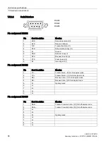
Page 68: ...t ready I 7 RTS Request to send O 8 CTS Clear to send I 9 RI Incoming call I Pin assignment RS422 Pin Short description Meaning 1 TX Transmit data O for full duplex mode 2 TX Transmit data O for full duplex mode 3 RX Receive data I for full duplex mode 4 RX Receive data I for full duplex mode 5 M Signal ground 6 nc 7 nc 8 nc 9 nc Pin assignment RS485 Pin Short description Meaning 1 Data Transmit r...

Page 69: ...e Meaning Input output 1 VBUS 5 V fused Output 2 D Data channel USB2 Input output 3 D Data channel USB2 Input output 4 GND Ground 5 RX Data channel USB3 Input 6 RX Data channel USB3 Input 7 GND Ground 8 TX Data channel USB3 Output 9 TX Data channel USB3 Output 7 5 2 5 DisplayPort Pin Short name Meaning Input output 1 ML_Lane0 DP data 0 Output 2 GND Ground 3 ML_Lane0 DP data 0 Output 4 ML_Lane1 DP ...

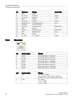
Page 70: ...etect Input 19 GND Ground 20 DP_PWR 3 3V fused Output 7 5 2 6 Ethernet port Pin Short description Meaning 1 BI_DA Bidirectional data A input output 2 BI_DA Bidirectional data A input output 3 BI_DB Bidirectional data B input output 4 BI_DC Bidirectional data C input output 5 BI_DC Bidirectional data C input output 6 BI_DB Bidirectional data B input output 7 BI_DD Bidirectional data D input output ...

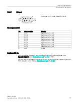
Page 71: ...Input or Output 3 4 DIO_4 Digital Input or Output 4 5 DIO_5 Digital Input or Output 5 6 DIO_6 Digital Input or Output 6 7 DIO_7 Digital Input or Output 7 8 DIO_8 Digital Input or Output 8 9 GND Ground Configure DIO pin You can configure the state of each DIO pin as Input mode or Output mode in the Dynamic Digital IO page of Advanced menu Page 80 in BIOS The DIO setting tool helps you to configure ...

Page 72: ... Range GPIO40 to GPIO47 Set GPIO47 to Output High GpioSetting GPIO47 O H Set GPIO47 to Output Low GpioSetting GPIO47 O L Set GPIO47 to Input GpioSetting GPIO47 I 2 Mode O Output I Input 3 Status H High L Low Show the specified GPIO GpioSetting Parameter1 S For example Show GPIO47 GpioSetting GPIO47 S Show GPIO40 47 GpioSetting ALL 3 According to the return value to determine whether the modificati...

Page 73: ..._RXN 29 32 UIM_CLK I PERP1 USB3 0_RX SSIC_RXP 31 34 UIM_DATA IO GND5 33 36 UIM_PWR I PETN1 USB3 0_TX SSIC_TXN 35 38 DEVSLP O 0 3 3V PETP1 USB3 0_TX SSIC_TXP 37 40 GNSS0 0 1 8V GND6 39 42 GNSS1 0 1 8V PERN0 SATA_B 41 44 GNSS2 0 1 8V PERP0 SATA_B 43 46 GNSS3 0 1 8V GND7 45 48 GNSS4 0 1 8V PETN0 SATA_A 47 50 PERST O 0 3 3V PETP0 SATA_A 49 52 CLKREQ IO 0 3 3V GND8 51 54 PEWAKE IO 0 3 3V REFCLKN 53 56 ...

Page 74: ...S setup utility Aptio TSE The BIOS is developed on AMI based code AMI provides AptioTM Text Setup Environment TSE a test based basic input and output system as BIOS setup utility The purpose of AptioTM TSE is to empower the user with complete system control at boot Getting BIOS setup To enter BIOS Setup at startup 1 Power on the device 2 Press DELETE or ESC key on your keyboard during the Power On...

Page 75: ...bar The menu bar is on the top of the screen and has the following main items Main For changing the basic system configuration Advanced For changing the advanced system settings Hardware Monitor For displaying the system temperature power status and changing the fan settings Boot For changing the system boot configuration Save Exit For selecting the exit options and loading default settings Functi...

Page 76: ...eral help window F2 Previous Values Enable user to load previous values in BIOS setup Menu F3 Optimized Defaults Enable user to load optimized default values in BIOS Setup Menu F4 Save Exit Enable user to save the current configuration and exit BIOS Setup Menu ESC Right Click Exit The ESC Key or Right Click allows you to discard any change have made and exit BIOS setup menu Configuration fields Co...

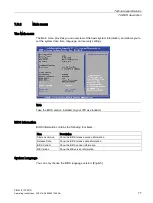
Page 77: ... time language and security settings Note Take the BIOS version installed on your IPC as standard BIOS information BIOS Information contains the following four items Item Description Siemens Version Show the BIOS release version information Release Date Show the BIOS release date information BIOS Vendor Show the BIOS vendor information ME Version Show the ME version information System Language You...

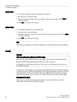
Page 78: ...uld enter 06 30 00 for 6 30 AM Security NOTICE Risk of unauthorized modification for BIOS setting Everyone can access BIOS and change its setting if you don t set a password for BIOS Modify the BIOS setting arbitrarily may interfere with device function Set passwords for administrator and user In this way to avoid unauthorized access and modification to BIOS The Password menu allows you to change ...

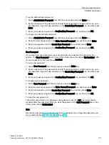
Page 79: ...ord item on top of the screen shows the default Not Installed After you set a password this item shows Installed To set a user password 1 Select User Password with the arrow keys and press Enter key 2 Enter a password The password of at least three characters in length and can be up to 20 characters long and case sensitive in the Create New Password box and then press Enter 3 Enter your password a...

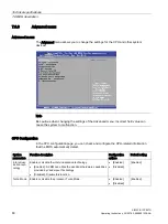
Page 80: ...malfunction CPU Configuration In the CPU configuration page you can check and configure the CPU related information that the BIOS automatically detect System parameters Function description Configuration options Default setting Intel virtual ization tech nology Enable or disable the intel virtualization technology Enabled A VMM can utilize the additional hardware capabilities provided by Vanderpoo...

Page 81: ...PEG CPU Graphics iGPU Multi Monitor Enable or disable the iGPU Multi Monitor Enabled To empower both integrated and discrete graphics The iGPU shared system memory size will be fixed at 64MB Disabled Disable this function Enabled Disabled Disabled IGD Minimum Memory Select DVMT 5 0 Pre_Allocated Fixed Graphics Memory size used by the Internal Graphics Device 32M 64M 96M 1024M 128M Audio Controller...

Page 82: ...Hot Plug Enable or disable the SATA Hot Plug Support Enabled Disabled Disabled USB Configuration In the USB Configuration page you can change the USB related features System parameters Function description Configuration options Default setting USB Port Per Port Control Enable or disable the USB ports individually LAN1_U31G1_1 x60 LAN1_U31G1_2 x61 LAN2_U31G1_3 x62 LAN2_U31G1_4 x63 USB5 9 Enabled Di...

Page 83: ...N function of the onboard LAN controller or the PCIE LAN cards Enabled Disabled Disabled Resume from USB in S5 State Enable or disable Resume from USB in S5 state Enabled Disabled Disabled Dynamic Digital IO In the Dynamic Digital IO page you can configure Digital IO DIO0 DIO7 settings There are two configuration options Input and Output and the default setting is Input Serial Port Configuration I...

Page 84: ...perating mode RS232 RS422 RS485 RS232 Serial Port 3 Configuration Serial Port 3 Enable or disable the serial port COM 3 Enabled Disabled Enabled Change Set tings When you set the Serial Port 3 to Ena bled and allows you to select the Serial Port base address Auto IO 3E8h IRQ 7 IO 3E8h IRQ 3 4 5 6 7 8 9 10 11 12 IO 2E8h IRQ 3 4 5 6 7 8 9 10 11 12 IO 2F0h IRQ 3 4 5 6 7 8 9 10 11 12 IO 2E0h IRQ 3 4 5...

Page 85: ...AN2 Enabled Disabled Enabled INTEL LAN2 PXE OPROM Enable or disable the INTEL LAN2 PXE OPROM Enabled Disabled Disabled Add on PCIE LAN Card PXE Boot Enable or disable the Add on PCIE LAN Card PXE Boot Enabled Disabled Disabled Charging USB de vice in Power State S5 Enable or disable the charging USB devices even when the system is in Power State S5 Enabled Disabled Enabled Network Stack Configurat...

Page 86: ... setting PCIEX16 Enable or disable the PCIEX16 Enabled Disabled Enabled PCIEX16 Speed Configure PCIEX16 Gen1 Gen3 Auto Gen1 Gen2 Gen3 Auto PCIEX16 Non Compliance mode Detect Non Compliance PCI Express Device in PCIEX16 Enabled Disabled Disabled PCIEX4 Enable or disable the PCIEX4 Enabled Disabled Enabled PCIEX4 Speed Configure PCIEX4 Gen1 Gen3 Auto Gen1 Gen2 Auto PCIEX4 Non Compliance mode Detect ...

Page 87: ...peeds in rotations per minute RPM If the fan is not connected to the motherboard the field shows N A Select Ignore if you do not need to display the de tected speed xxxx RPM Ignore N A N A CPU VCORE 3 3V 5V 12V The onboard hardware monitor automatically detects the voltage output through the onboard voltage regulators Select Ignore if you do not want to detect this item Actual Value Actual Value C...

Page 88: ...ot speed Enabled Select to accelerate the boot speed Disabled Select to go back to normal boot Enabled Disabled Disabled If you select Enable the Next Boot after AC Power Loss item appears Normal Boot Returns to normal boot on the next boot after AC power loss Fast Boot Accelerates the boot speed on the next boot after AC power loss Normal Boot Fast Boot Normal Boot Boot mode se lect Select the de...

Page 89: ...stem parameters Function description Configuration options Default setting Launch CSM Enable or disable the CSM Enabled Disabled Enabled Boot mode select Select the devices boot up mode by the devices specification Devices with the selected mode will appear in the boot priority list Legacy Legacy only Legacy Boot from Network Devices Select the type of the onboard LAN controllers and installed LAN...

Page 90: ... SIEMENS Logo appears Access Windows OS in Safe Mode press F8 after POST 7 6 6 Save Exit menu Save Exit menu The Save Exit menu allows you to load the optimal default values for the BIOS items and save or discard your changes to the BIOS items Save Changes and Reset When you complete the system configuration changes save the changes with the following steps 1 Select Save Changes and Reset with the...

Page 91: ...s Enter key to the load optimized defaults Or Select No to quit Save as User Defaults This option saves current configuration as User Defaults You can save your settings as user default settings with the following steps 1 Select Save as User Defaults with the arrow keys and press Enter key 2 Select Yes and press Enter key to save the settings as user defaults Or Select No to quit Restore User Defa...

Page 92: ...etely disconnect the power cord from your motherboard when you are working on it Do not make connections while the power is on because a sudden rush of power can damage the sensitive electronic components Always ground yourself to remove any static charge before touching the board Modern electronic devices are very sensitive to static electric charges Use a grounding wrist strap at all times Place...

Page 93: ... all the attached hardware components are connected Turning on the power before you connected them the motherboard and the system components may get damaged and injure operator Make sure you securely attached the hardware components to the motherboard connectors slots sockets The screws are not allowed to connect with motherboard circuit or components The motherboard can be get damaged by this act...

Page 94: ...Appendix Motherboard A 1 Jumpers SIMATIC IPC527G 94 Operating Instructions 03 2019 A5E45491226 AA Clear CMOS Note Set the jumper back to protected mode after clearing CMOS ...

Page 95: ...Appendix Motherboard A 1 Jumpers SIMATIC IPC527G Operating Instructions 03 2019 A5E45491226 AA 95 COM1 COM2 Ring 5V 12V selection 6 pin COM1_SEL COM2_SEL Intel ME jumper 3 pin DIS_ME ...

Page 96: ...96 Operating Instructions 03 2019 A5E45491226 AA A 2 Internal Connector A 2 1 Intel H110 Serial ATA 6 0Gb s connectors SATA6G_1 2 Intel H110 Serial ATA 6 0 Gb s connectors connect to Serial ATA 6 0 Gb s hard disk drives through Serial ATA 6 0 Gb s signal cables ...

Page 97: ...the fan connectors on the motherboard ensuring that the black wire of each cable matches the ground pin of the connector Note In order to prevent the damage from insufficient air flow inside the system to motherboard components connect the fan cables to the fan connectors Do not place jumper caps on the fan connectors The CPU_FAN connector supports a CPU fan of maximum 1A 12 W fan power ...

Page 98: ...ly fit Note Connect the 6 pin power plug to provide power to the riser card Siemens recommends that you use an ATX 12V Specification 2 0 compliant or later version power supply unit PSU with a minimum of 350W power rating This PSU type has 24 pin and 4 pin power plugs The 4 Pin ATX 12 V power plug must be connected otherwise the system cannot be booted up Siemens recommends that you use a PSU with...

Page 99: ...O Digital I O connector includes 8 I O lines In Out programmable All of the Digital I O lines are programmable and each I O pin can be individually programmed to support various devices Note To configure the I O pins in BIOS navigate to Dynamic Digital IO selection in Advanced tab For the detailed information refer to Advanced menu Page 80 ...

Page 100: ...00 Operating Instructions 03 2019 A5E45491226 AA A 2 5 Serial port connectors COM3 COM4 These connectors are for serial COM ports Connect the serial port module cable to these connectors then install the module to a slot opening at the back of the system chassis ...

Page 101: ...MATIC IPC527G Operating Instructions 03 2019 A5E45491226 AA 101 A 2 6 M 2 B Key slot This socket allows you to install an M 2 module For the detailed information refer to M 2 interface Page 73 Note This slot supports type 2242 SATA storage devices ...

Page 102: ... 2019 A5E45491226 AA A 2 7 USB 2 0 connectors USB56 USB78 USB9 Connect a USB module cable to any of these connectors then install the module to a slot opening at the back of the system chassis This USB connectors comply with USB 2 0 specifications and support up to 480Mbps connection speed ...

Page 103: ...ower LED lights up when you turn on the system power and blinks when the system is in sleep mode Hard disk drive activity LED 2 pin HDD_LED This 2 pin connector is for the HDD Activity LED Connect the HDD Activity LED cable to this connector The HDD LED lights up or flashes when data is read from or written to the HDD ATX power button soft off button 2 pin PWR_BTN This connector is for the system ...

Page 104: ...w siemens com simatic tech doku portal Your local representative http w3 siemens com aspa_app Training center http sitrain automation siemens com sitrainworld AppLang en Industry Mall https mall industry siemens com When contacting your local representative or Technical Support please have the following information at hand MLFB of the device BIOS version for industrial PC or image version of the d...

Page 105: ...ected Check whether the power cord has been properly connected to the monitor and to the system unit or to the grounded shockproof outlet Check whether the monitor cable has been properly connected to the system unit and to the monitor If the monitor screen still remains dark after you have performed these checks and measures con tact your technical support team The mouse pointer does not appear o...

Page 106: ...r levels Different pin assignment Check your computer configuration If the computer configuration corresponds to the delivery state contact your technical support team If the configuration has changed restore the factory state To do this remove the third party modules and restart the device If the error no longer occurs the third party module being used was the cause of the fault Replace the thrid...

Page 107: ...symbols on your device may vary in some details from the symbols shown in the following tables C 2 Safety Symbol Meaning Symbol Meaning Warning observe the supplied docu mentation Lock is closed Attention radio equipment Lock is open Disconnect the power plug before opening Opening for Kensington lock Attention ESD Electrostatic sensitive device Warning of hot surface C 3 Operator controls Symbol ...

Page 108: ... more information in the operating instructions for your device Symbol Meaning Symbol Meaning Approved for Australia and New Zea land Marking for the Eurasian Customs Union Approved for China Test mark of Factory Mutual Re search CE markings for European countries Marking of Federal Communications Commission for the USA EFUP Environment Friendly Use Period marking for China Approved for Korea Test...

Page 109: ...e Protective conductor terminal PS 2 keyboard interface Connection for functional earthing equipotential bonding line Multimedia Card Reader DisplayPort interface Smart Card Reader DVI D interface Line In LAN interface not approved for con necting WAN or telephone Line Out Serial port Microphone input USB port Universal Audio Jack USB 2 0 high speed port Headphone output USB 3 0 super speed port ...

Page 110: ...utput System CAN Controller Area Network CD ROM Compact Disc Read Only Memory CE Communauté Européenne CF CompactFlash CMOS Complementary Metal Oxide Semiconductors COA Certificate of authentication COM Communications Port Term for the serial interface CPU Central Processing Unit CPU CSA Canadian Standards Association Canadian organization for tests and certifica tions according to national or bin...

Page 111: ...ernational Electronical Com mission IGD Integrated Graphics Device IP International Protection in English speaking countries Ingress Protection Degree of protection IRQ Interrupt Request ISA Industry Standard Architecture Bus for expansion modules LAN Local Area Network Computer network that is limited to a local area LEDs Light Emitting Diode Light emitting diode LPS Limited Power Source MAC Medi...

Page 112: ...C Real Time Clock Real time clock RTS Request to send Request to send RxD Receive Data Data transfer signal SATA Serial Advanced Technology Attachment SCU Setup Configuration Utility SELV Safety Extra Low Voltage Safety extra low voltage SMART Self Monitoring Analysis and Reporting Technology Hard disk error diagnostics program SRAM Static Random Access Memory Static RAM SSD Solid State Drive TFT ...

Page 113: ...erating Instructions 03 2019 A5E45491226 AA 113 VT d Virtualization Technology for Directed I O Enables the direct assignment of a device e g network adapter to a virtual device WD Watchdog Program monitoring with error detection and alarming ...

Page 114: ...nd non replaceable data against loss when the working copy is corrupted Certain applications automatically generate backup copies of data files and manage both the current and the previous versions on the hard disk Baud Physical unit for the step speed in signal transmission Defines the number of transferred signal states per second With only two states one baud is equivalent to a transmission rat...

Page 115: ...ms CF I 42 6 x 36 4 x 3 3 mm and CF II 42 8 x 36 4 x 5 mm Configuration files These are files containing data which define the configuration after restart Examples of such files are CONFIG SYS AUTOEXEC BAT and the registry files Configuration software The configuration software updates the device configuration when new modules are installed This is done either by copying the configuration files su...

Page 116: ...ons The energy options can be used to reduce energy consumption of the computer while keeping it ready for immediate use This can be configured in Windows by selecting Settings Control Panel Energy options Enhanced Write Filter Configurable write filter that allows you to for example boot Windows Embedded Standard from write protected media e g CD ROM set write protection for individual partitions...

Page 117: ...oration of a uniform saved system state when booting This minimizes write access for example to a memory card when you start up and shut down Windows Embedded Standard 7 Hub A term in network technology In a network a device joining communication lines at a central location providing a common connection to all devices on the network Hyper Threading HT technology multi threading enables the paralle...

Page 118: ...Legacy Boot Device Conventional drives can be used as USB devices License key The license key represents the electronic license stamp of a license Siemens AG issues a license key for each software that is protected by a license License key USB flash drive The license key USB flash drive contains the authorizations or license keys required to enable protected SIMATIC software Low voltage directive ...

Page 119: ...nsion card POST Self test performed by the BIOS after the computer is switched on Performs a RAM test and a graphics controller test for example The system outputs audible signals beep codes if the BIOS detects any errors the relevant message indicating cause of error is output on the screen Programmable controller The programmable controllers of the SIMATIC S7 system consist of a central controll...

Page 120: ...ion of the PC PG is preset with defaults Changes must therefore be entered in the SETUP if a memory expansion new modules or a new drive are added to the hardware configuration SSD Solid State Drive A Solid State Drive is a drive that can be installed like any other drive it does not contain a rotating disk or other moving parts because only semiconductor memory chips of similar capacity will be u...

Page 121: ...erating Instructions 03 2019 A5E45491226 AA 121 Warm restart The restart of a computer after a program was aborted The operating system is loaded and restarted again The CTRL ALT DEL hotkey can be used to initiate a warm restart ...

Page 122: ...sk mounting 23 Desk mounting and Wall mounting 60 Device Closing 37 Open 37 Device fan 46 Directive ESD Directive 58 Disk drive Installing 44 Removing 44 DisplayPort Interface 69 Drive 64 E EAC 57 ESD 58 ESD Directive 58 Ethernet 31 67 Ethernet address 19 Expansion slot 63 Extension card Installing 39 Removing 39 F FCC 56 Firewall 35 Front view 10 function earth 27 Connecting 27 G General technica...

Page 123: ...rotection class 62 Protective measure Static electricity 60 R Radiation 15 High frequency radiation 15 RAM 63 Real time protection 35 Rear view 11 Repairs 45 46 Riser card Installing 40 Removing 40 S Safety information Storage 18 Transportation 18 Serial number 18 SIMATIC NET 31 SIMATIC S7 31 Integration 31 Static electricity Protective measures 60 Supply voltage 8 62 Switching off the device Disc...

Reviews: