background image


Appendix 


A.2 Certificates and Approvals 

SIMATIC IPC847C 
Getting Started, 12/2010, A5E02669190-02 

43


EMC  


USA 
Federal Communications 

Commission 
Radio Frequency 

Interference Statement 

This equipment has been tested and found to comply with the limits for a 

Class A digital device, pursuant to Part 15 of the FCC Rules. These limits 

are designed to provide reasonable protection against harmful 

interference when the equipment is operated in a commercial 

environment. This equipment generates, uses, and can radiate radio 

frequency energy and, if not installed and used in accordance with the 

instruction manual, may cause harmful interference to radio 

communications. Operation of this equipment in a residential area is likely 

to cause harmful interference in which case the user will be required to 

correct the interference at his own expense.  

Shielded cables 

Shielded cables must be used with this equipment to maintain compliance 

with FCC regulations. 

Modifications 

Changes or modifications not expressly approved by the manufacturer 

could void the user's authority to operate the equipment. 

Conditions of operations  This device complies with Part 15 of the FCC Rules. Operation is subject 

to the following two conditions: (1) this device may not cause harmful 

interference, and (2) this device must tolerate any interference received, 

including interference that may cause undesired operation. 


CANADA 
Canadian Notice 

This Class B digital apparatus complies with Canadian ICES-003. 

Avis Canadian 

Cet appareil numérique de la classe B est conforme à la norme NMB-003 

du Canada. 


AUSTRALIA 


This product meets the requirements of the standard EN 61000-6-3:2007 

Generic standards - Emission standard for residential, commercial and 

light-industrial environments. 

Summary of Contents for SIMATIC IPC847C

Page 1: ...________ ___________________ ___________________ ___________________ ___________________ SIMATIC Industrial PC SIMATIC IPC847C Getting Started 12 2010 A5E02669190 02 Introduction 1 Description 2 Application planning 3 Installing 4 Connection 5 Commissioning 6 Troubleshooting 7 Dimension drawings 8 Appendix A ...

Page 2: ...the relevant documentation for the specific task in particular its warning notices and safety instructions Qualified personnel are those who based on their training and experience are capable of identifying risks and avoiding potential hazards when working with these products systems Proper use of Siemens products Note the following WARNING Siemens products may only be used for the applications de...

Page 3: ...Technical data of the telescopic rails 22 5 Connection 23 5 1 Connecting peripherals 23 5 2 Connecting the device to power 24 5 3 Equipotential bonding 28 5 4 Strain relief for network cables 29 6 Commissioning 31 6 1 Requirements for commissioning 31 6 2 Initial Commissioning Initial Startup 32 6 3 Reinstalling the software 33 7 Troubleshooting 35 7 1 General problems 35 8 Dimension drawings 39 8...

Page 4: ...Table of contents SIMATIC IPC847C 4 Getting Started 12 2010 A5E02669190 02 ...

Page 5: ...d print the operating instructions run Start and follow the instructions on the screen The operating instructions provide useful information on many topics such as the hardware expansion options modification of the system configuration and technical data Conventions The term rack PC or device is sometimes used to refer to the SIMATIC IPC847C product in this documentation The abbreviation CP stands...

Page 6: ...Introduction SIMATIC IPC847C 6 Getting Started 12 2010 A5E02669190 02 ...

Page 7: ...tatus displays Cover screws On off button Reset button Lock Features for the installation of DVD ROM drives DVD burners and removable racks Installation option for 3 5 drive 2 x USB interface Lockable front door for access security Keep the front door closed during normal operation Rear view of the device example Item Description Rear drive cooling fan Modules of the redundant power supply optiona...

Page 8: ... for switching the device on or off Note The device rear has one or 2 line side switches These have to be switched on so that the on off button at the front functions Reset button The reset button can be operated using a pointed object or a paper clip for example The button signal triggers a hardware reset The PC performs a restart cold start On Off switch Used to connect the device to the mains D...

Page 9: ...Reset button Item Description On Off switch Used to connect the device to the mains Depending on the BIOS set up entry After Power Failure the PC switches on automatically or the On Off button on the front has to be pressed Acknowledgement button of the redundant power supply The acoustic error signal is deactivated when the button is pressed ...

Page 10: ...Description 2 3 Connecting elements SIMATIC IPC847C 10 Getting Started 12 2010 A5E02669190 02 2 3 Connecting elements Interfaces Layout of the interfaces on the rear of the device ...

Page 11: ...ace 25 pin DP 2 x display port DP connection of Dual Head graphics card optional KEYBOARD Connection for a PS 2 keyboard MOUSE Connection for a PS 2 mouse DVI I DVI VGA port for CRT or LCD monitor with DVI interface VGA via DVI VGA adapter Audio input Connection for analog audio source microphone 3 5 mm phono jack Audio output Connection for active speakers or headset 3 5 mm phono jack DVI D DVI D...

Page 12: ...n of the connector for cooling devices Description Connector for cooling devices of the AC power supply to the device The permitted power range is 100 VAC to 240 VAC Connector for cooling devices at redundant power supply for the AC power supply of the device The permitted power range amounts to 100 VAC to 240 VAC ...

Page 13: ...LEDs Description OFF isolated from mains YELLOW Standby hibernating POWER PC status display GREEN PC in operation OFF no access HDD Display for hard disk access GREEN Access OFF No connection No data traffic ETHERNET 1 ETHERNET status display GREEN Data traffic OFF No connection No data traffic ETHERNET 2 ETHERNET status display GREEN Data traffic ...

Page 14: ... Diagnostics information available No communication established OFF WATCHDOG not activated GREEN WATCHDOG monitoring enabled WATCHDOG WATCHDOG status display RED Monitoring time elapsed OFF Internal temperature OK TEMP Internal temperature monitoring RED Internal temperature critical OFF Fan speed OK FAN Fan status only with active DiagBase or DiagMonitor software RED Fan speed too low OFF RAID is...

Page 15: ... Cable disabled Interface disabled Green LED Link status display of CP 1616 channel GREEN Active cable connected OFF No cable connected Cable disabled Interface disabled No activity PROFINET LAN X1 P1 P2 P3 Yellow LED Activity status display of CP 1616 channel YELLOW Data transfer active For unique labeling the LAN and PROFINET interfaces are numbered on the housing The numbering by the operating ...

Page 16: ...Description 2 4 Status displays SIMATIC IPC847C 16 Getting Started 12 2010 A5E02669190 02 ...

Page 17: ...or inside the device If condensation has developed on the device wait at least 12 hours before you switch it on 3 2 Unpacking and checking the delivery unit Unpacking the device Note the following points when you unpack the unit It is advisable not to dispose of the original packing material Keep it in case you have to transport the unit again Please keep the documentation in a safe place It is re...

Page 18: ...he front door Figure 3 1 Rating plate Order number of the device Device Ethernet address The Ethernet address is printed on the device and is stored in the BIOS Setup F2 key under Advanced Peripheral Configuration Microsoft Windows Product Key on the Certificate of Authenticity COA The COA label is attached to the inside of the front door You may need the Product Key in case you reinstall the oper...

Page 19: ...are subject to caustic vapors or gases without taking additional protective measures such as the provision of clean air Do not expose the device to direct sunlight Install the device in such a way that it poses no danger for example by falling over The device conforms to protection class IP41 at the front panel Ensure that the installation opening for the device is splash proof in areas which may ...

Page 20: ...Application planning 3 4 Access protection SIMATIC IPC847C 20 Getting Started 12 2010 A5E02669190 02 ...

Page 21: ...at identified by the necessary risk analysis The intended use of the device has to be ensured The proper use of the device has to be verified with a function test on the system This test can detect programming configuration and wiring errors The test results have to be documented and if necessary inserted into the relevant inputs Options of mounting the device Mounting on cabinet brackets Mounting...

Page 22: ...he 19 inch brackets of the front panel Note For vertical operation install the device on a horizontal metal base and secure it against tilting The following RITTAL module panels are available Rittal type TE 7000 620 Rittal type VR 3861 580 Rittal type DK 7063 710 Note the information of the switch cabinet supplier 4 2 Technical data of the telescopic rails Ultimate load per pair At least 23 kg Ful...

Page 23: ...been disconnected from the power supply CAUTION Strictly adhere to the specifications in the I O manuals NOTICE The connected or built in peripherals should not introduce a counter emf into the device A counter emf greater than 0 5 V to ground on the 3 3 VDC 5 VDC 12 VDC power rail due to a connected or integrated component can prevent normal operation or even destroy the computer When measuring t...

Page 24: ...ct switch must be installed if the device is mounted in a switch cabinet Always ensure free and easy access to the power inlet on the device or that the safety power outlet of the building installation is freely accessible and located close to the device Note The wide range power supply module is designed for operation on 100 VAC to 240 VAC mains The setting of the voltage range takes place automa...

Page 25: ...regulations and stipulated IDs of the country where the system is to be installed For the USA and Canada For the United States and Canada a CSA or UL listed power cord must be used The connector must be compliant with NEMA 5 15 120 V AC power supply To be used is a flexible power cord approved to UL and with CSA label and which has the following features Type SJT with three leads min 18 AWG conduc...

Page 26: ...g the device to mains 1 Ensure that the ON OFF switch is in 0 position Off when you plug in the power cord to avoid unintentional startup of the device 2 Plug in the connector of the cooling device 3 Connect the power cable to the socket and turn on the ON OFF switch The yellow power LED standby on the front panel of the PC lights up ...

Page 27: ...id unintentional disconnection of the power cord Steps for securing the power plug 1 Screw out the lower left hand fixing screw on the power supply unit 2 Screw on the lock for the mains connector 1 to the power supply unit WARNING If the power plug is secured with a clamp the power outlet must be freely accessible to allow the device to be easily removed from the mains ...

Page 28: ...tched on or connected or a module is defective a warning signal is emitted You cancel the warning signal by pressing button 5 3 Equipotential bonding A low impedance ground connection improves the discharge of interference generated by external power cables signal cables or cables for I O modules to ground Equipotential bonding terminal The equipotential bonding terminal on the device large surfac...

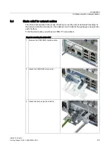
Page 29: ...scope of delivery is used to prevent accidental loosening of the network cable from the device One cable tie not included in the package is required for each interface To fix the strain relief you will need a TORX T10 screwdriver Steps for mounting the strain relief 1 Remove the PROFINET interface plate 2 Attach the PROFINET strain relief 3 Attach the cable using the cable tie ...

Page 30: ...Connection 5 4 Strain relief for network cables SIMATIC IPC847C 30 Getting Started 12 2010 A5E02669190 02 ...

Page 31: ... on The device is equipped with a power supply unit with line side switch In the line side switch position 1 the device can be switched on by using the On Off switch at the front If the line side switch is in the position 0 the device draws the lowest power from the AC power supply It cannot be switched on by using the On Off switch at the front Before you switch on the device you should verify th...

Page 32: ...he operating system setup may become corrupted 4 Automatic restart After you have entered all necessary information and after the operating system setup is completed the PC is automatically restarted and displays the user interface of the relevant operating system From now on after you switch on the PC the user interface of the operating system is automatically opened when the startup routine is c...

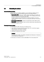
Page 33: ...ant to integrate additional languages you will need to subsequently install them from Recovery CD 2 or DVD Documentation and Drivers CD Contains the documentation and the hardware drivers Restore DVD Contains a hard disk image file with the original software operating system with installed hardware drivers Restoring the factory condition Place the Restore DVD into the drive and restart the device ...

Page 34: ...Commissioning 6 3 Reinstalling the software SIMATIC IPC847C 34 Getting Started 12 2010 A5E02669190 02 ...

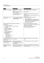
Page 35: ...d outlet Check whether the monitor cable has been properly connected to the system unit and to the monitor The external monitor remains dark Power cord or monitor cable not connected If the monitor screen still remains dark after you have performed these checks please contact your technical support team The mouse driver is not loaded Check whether the mouse driver is properly installed and present...

Page 36: ...is not installed The Serial ATA plug in failed to load because the driver is not installed correctly The Intel Matrix Storage Console was unable to load a page for the following reason A plug in did not provide a page for the selected device A plug in failed to load RAID is not activated RAID is activated In this case the messages have no negative influence on the device function and can be ignore...

Page 37: ... reports that hard disk 1 is defective Section RAID monitoring Red HDD2 ALARM LED is lit RAID reports that hard disk 2 is defective Section RAID monitoring Red HDD1 ALARM and HDD2 ALARM LEDs are flashing RAID is in the rebuild state Section RAID monitoring Red HDD1 ALARM and HDD2 ALARM LEDs are lit RAID system is not ready for operation Affected drive must be determined with the help of the RAID s...

Page 38: ...Troubleshooting 7 1 General problems SIMATIC IPC847C 38 Getting Started 12 2010 A5E02669190 02 ...

Page 39: ...s 8 8 1 Dimensional drawing of the device SIEMENS SIMATIC RACK PC HDD2 ALARM HDD1 ALARM FAN TEMP WATCHDOG PROFIBUS MPI ETHERNET 2 ETHERNET 1 HDD POWER 8QLWV RI PHDVXUHPHQW 7RS LQ YHUWLFDO PRXQWLQJ SRVLWLRQ 7RS LQ YHUWLFDO PRXQWLQJ SRVLWLRQ PP ROO Figure 8 1 Dimensional drawing ...

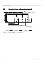
Page 40: ...elescopic rails 8QLWV RI PHDVXUHPHQW PP LQFKHV 7 WROHUDQFH RI s PP LQFKHV 7 WROHUDQFH RI s PP LQFKHV 7 WROHUDQFH RI s PP LQFKHV LPHQVLRQV IRU WKH 5LWWDO WHOHVFRSLF UDLOV 7 SH 53 IRU PP FDELQHW 7 SH 53 IRU PP FDELQHW LPHQVLRQV IRU 6FKURII WHOHVFRSLF UDLO W SH s7 s7 s7 s7 s7 s7 s7 s7 s7 s7 s7 s7 s7 s7 s7 s7 s7 s7 Figure 8 2 Dimensional drawing for the use of telescopic rails ...

Page 41: ...6 3 2007 EN 61000 6 1 2007 Industry EN 61000 6 4 2007 EN 61000 6 2 2005 The product complies with EN 61000 3 2 2006 harmonic currents and EN 61000 3 3 2008 voltage fluctuations and flicker Low voltage directive The product fulfills the requirements of EC Directive 2006 95 EC Low Voltage Directive Conformance with this directive has been verified according to EN 60950 1 2006 Declaration of conformi...

Page 42: ... processes development production and sales meets ISO 9001 2000 requirements This has been certified by DQS the German society for the certification of quality management systems Q Net certificate no DE 001108 QM Software License Agreement The device can be supplied with or without preinstalled software For devices with preinstalled software please note the relevant license agreements Approvals fo...

Page 43: ...ser will be required to correct the interference at his own expense Shielded cables Shielded cables must be used with this equipment to maintain compliance with FCC regulations Modifications Changes or modifications not expressly approved by the manufacturer could void the user s authority to operate the equipment Conditions of operations This device complies with Part 15 of the FCC Rules Operatio...

Page 44: ... www sitrain com Technical support You can contact technical support for all Industry Automation and Drive Technologies products by E mail support automation siemens com Internet Online support request form http www siemens com automation support request When you contact the customer support please have the following information for the technician on hand BIOS version Order No MLFB of the device I...

Page 45: ...irective 41 43 Equipotential bonding 28 Error messages Troubleshooting 35 ETHERNET 13 Ethernet address 18 F FAN 14 Fans 7 Filter mat 7 Front door 7 Front view 7 I I O devices 23 Identification data 18 Initial commissioning 32 installation Installation locations 21 Mounting methods 21 Interfaces 10 COM 11 DVI D 11 DVI I 11 ETHERNET 11 KEYBOARD 11 KEYBOARD 11 LPT 11 MOUSE 11 PROFIBUS MPI 11 PROFINET...

Page 46: ...US MPI 11 Protection class 19 R Rating plate 7 Rear view 7 Reset button 7 8 Restart 32 S Secure the power plug 27 Serial number 18 Status displays 13 15 Ethernet 13 FAN 14 PROFIBUS MPI 14 TEMP 14 WATCHDOG 14 Strain relief Ethernet cable 29 Supply voltage 25 T Telescopic rails Mounting methods 21 Technical data 22 TEMP 14 Transport 17 Troubleshooting FAQs 35 U USB interface 7 V Ventilation slots 19...

Reviews: