Product overview
2.3 Power supply
PDC1000(F)
16
Equipment Manual, 02/2020, A5E48775040-AA
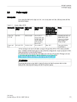
Power supply for the power unit
You must feed the power supply for the power unit via terminals 4L+ and 4M at the X5050
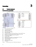
interface (Figure 3-1 Connections of PDC1000 drive controller with pin assignment
(Page 18)).
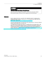
NOTICE
A two-pole miniature circuit breaker according to UL category DIVQ (UL 498) must be
inserted in the 4L+ and 4M feed line. You can find the article numbers of the miniature
circuit breakers to be used in the section "Accessories/Spare parts" in the System Manual
SIMATIC MICRO-DRIVE Drive controller PDC
https://support.industry.siemens.com/cs/ww/en/view/109774126
The miniature circuit breaker must be implemented with two poles even when using PELV.
In order for the DC link capacitors to be charged slowly when 4L+ is switched on, we
recommend a primary-switched electronic power supply with current limitation. Only the
required miniature circuit breaker has to be installed between the power supply and PDC,
and not an operational switch.
If 4L+ is switched on via a suitable miniature circuit breaker, the following characteristic
values result:
●
Peak current: < 300 A
●
Half value stream width: < 500
μ
s
NOTICE
The 4L+ input has no switch-on current limitation. Do not connect the terminals while live.
This must also be observed for any upstream switching devices or miniature circuit
breakers.
If, for operational reasons, the supply of 4L+ must be switched, we recommend
implementing an pre-charging input circuit on the installation side. After pre-charging is
finished, the pre-charging resistor must be bypassed by a suitable circuit before normal
operation is started.
Key data for the dimensioning:
●
Zero-signal current consumption 4L+: Approx. 15 mA (PDC not in operation)
●
Internal DC link capacitance: 4000
μ
F +/-20%
●
Pre-charging resistor is rated for the maximum voltage under fault conditions of the power
supply unit
≤
60 V
When energy recovery is activated, a supply voltage above 57.6 V DC is also permitted.
Use a suitable bi-directional supply to ensure that the voltage at 4L+ never exceeds
60 V DC during operation or under fault conditions.
●
The power of the pre-charging resistor must be rated for continuous power (voltage at the
pre-charging resistor is constantly equal to the maximum power supply voltage) or
appropriate measures must be taken to protect against overtemperature/overload.
Summary of Contents for SIMATIC MICRO-DRIVE PDC1000
Page 1: ...PDC1000 F ...

