background image

Alignment

SIMATIC MV230

Operating Instructions, 01/2007 Edition, A5E00749101-01

11

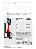
Determining the working distance

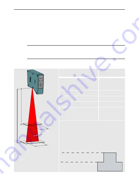
The SIMATIC MV230 height profile sensor has a specific laser line length 

(approx. 50 mm to approx. 75 mm) depending on the distance from the tested 

object. 

The distance (A) between sensor and object determines the length of the laser 

line (L):

 0.24 · A 

Example values

Note

The smaller the distance from the object, the better the resolution 

and thus the recognition of differences on the object.

Distance to sensor 

(mm)

Laser line 

length (mm)

210 (minimum distance 

from top edge of profile 

to sensor)

approx. 50

230

approx. 55

260

approx. 62

290

approx. 70

310 (maximum distance 

from bottom edge of pro-

file to sensor)

approx. 75

The height profile to be recorded must lie 

within the sensor's working range. This 

means that the distance between the tested 

profile and the sensor must be a minimum 

of 210 mm and a maximum of 310 mm 

since parts of the object outside this range 

cannot be recorded.

Working 
range of 
sensor

Ap

prox. 310

 m

m

Ap

prox. 2

10 mm

Approx. 50 mm

Approx. 75 mm

7RSHGJHRISURILOH

%RWWRPHGJHRISURILOH

7HVWSURILOH

2EMHFW

Summary of Contents for SIMATIC MV230

Page 1: ...simatic sensors SIMATIC MV230 Image Processing Systems Operating Instructions 01 2007 Edition ...

Page 2: ......

Page 3: ...SIMATIC Sensors Image processing systems SIMATIC MV230 Operating Instructions 01 2007 Edition A5E00749101 01 English ...

Page 4: ...Siemens AG Automation and Drives Postfach 48 48 90437 Nürnberg DEUTSCHLAND A5E00749101 01 01 2007 Edition Copyright Siemens AG 2007 Siemens AG 2007 Technical data subject to change ...

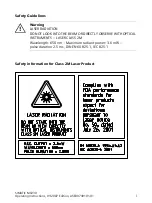
Page 5: ...i Safety Guidelines Safety information for Class 2M Laser Product Warning LASER RADIATION DO NOT LOOK INTO THE BEAM OR DIRECTLY OBSERVE WITH OPTICAL INSTRUMENTS LASER CLASS 2M Wavelength 650 nm Maximum radiant power 3 6 mW pulse duration 2 5 ms DIN EN 60825 1 IEC 825 1 ...

Page 6: ...e trademarks whose use by third parties for their own purposes may infringe the rights of the owner Liability disclaimer We have conscientiously checked the contents of this manual to ensure that they coincide with the hardware and software described Since deviations can not be precluded entirely we cannot guarantee full agreement The informa tion given in this publication is reviewed at regular i...

Page 7: ...odel selection and key disabling 8 Alignment 9 Operation 13 Start up 14 Overview of the steps in commissioning 14 Menu structure 15 Carry out basic settings Setting menu 17 Train model s Train menu 21 Test adjustments Test menu 25 Activate run mode Run menu 27 Model selection through SEL inputs 28 Info menu 29 Maintenance and service 31 Diagnostic messages 31 Technical specifications 34 Standards ...

Page 8: ...SIMATIC MV230 iv Operating Instructions 01 2007 Edition A5E00749101 01 ...

Page 9: ...0 6GF2110 0BA00 0AA0 1 Operating instructions Product name Machine Readable Product Code Support system for industrial sensors Support bar 200 mm 3RX7315 Support bar 300 mm 3RX7316 Device holder 3RX7326 Screw base 3RX7322 Preassembled connecting cables Connection to interface X1 M12 cable plug 8 pole with 5 m PUR cable 3RX8000 0CB81 1GF0 Connection to interface X2 M12 cable plug 8 pole with 5 m PU...

Page 10: ...pplication range The SIMATIC MV230 can be used for the following purposes Checking when filling packaging Placement checking of small parts Part recognition and checking for correct position during assembly The SIMATIC MV230 compares the height profile of the tested object with that of the trained model and provides information as to whether the inspection was successful or not It is possible to s...

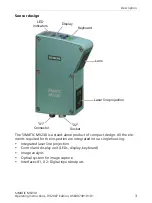
Page 11: ...ct of compact design All the ele ments required for the inspection are integrated into a single housing Integrated laser line projection Control and display unit LEDs display keyboard Image analysis Optical system for image capture Interfaces X1 X2 Digital inputs outputs LQGLFDWRUV LVSOD H ERDUG DVHU OLQH SURMHFWLRQ HQV RQQHFWRU 6RFNHW ...

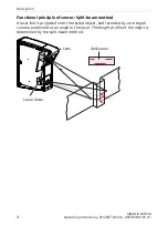
Page 12: ...49101 01 Functional principle of sensor Split beam method A laser line is projected onto the tested object and recorded by an integral camera positioned at an angle to the laser The height profile of the object is determined by the split beam method DVHU GLRGH HQV 6SOLW EHDP ...

Page 13: ...lation Mounting Mounting the SIMATIC MV230 M4 fixing holes see dimension drawing are used to mount the SIMATIC MV230 e g on the device holder of the support system The support system for industrial sensors is optionally available as an accessory Grounding the SIMATIC MV230 The SIMATIC MV230 can be grounded or non grounded In the grounded ver sion at least two fixing holes have to be connected with...

Page 14: ...cting The sensor is connected to a 24 V DC power supply Safety measures The SIMATIC MV230 must be powered by a safely isolated voltage 20 4 V to 28 8 V DC and a fuse according to UL248 14 4 A fitted on the installation side Power supply using an NEC Class2 unit is alternatively possible ...

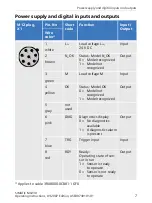
Page 15: ... L 24 V DC Input white 2 N_OK Status Model N_OK 0 Model recognized 1 Model not recognized Output brown 3 M Load voltage M Input green 4 OK Status Model OK 0 Model not recognized 1 Model recognized Output yellow 5 not used gray 6 DIAG Diagnostics display 0 No diagnostics available 1 A diagnostics alarm is present Output pink 7 TRG Trigger input Input blue 8 RDY Ready Operating state of sen sor in r...

Page 16: ...cket X2 Pin No Short code Function Input Output Wire color 1 not used white 2 SEL0 Select 0 Model selection Bit 0 Input brown 3 SEL1 Select 1 Model selection Bit 1 Input green 4 SEL2 Select 2 Model selection Bit 2 Input yellow 5 SEL3 Select 3 Model selection Bit 3 Input gray 6 DISA Disable Disabling manual key operation 0 Operation enabled 1 Operation disabled Input pink 7 not used blue 8 not used...

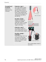
Page 17: ... the tested object This can be carried out under Setting See Sec tion Basic settings Line Length Object feeding with correct alignment The object must be fed with the correct alignment A small tolerance with respect to an offset along the laser line is permissible 1 mm and does not influ ence the result Avoid widely varying lighting effects and reflections Provide shading where lighting varies gre...

Page 18: ...ly recog nized and evaluated by the MV230 Possible remedy Position the object as centrally as possible under the sensor or align the sensor beam at an angle to this area Split beam Occlusion case 2 The profile in areas of deep indentations cannot be recorded by the object Possible remedy reduction If possible align sensor at an angle such that the laser line and optical axis meet at a uniform angl...

Page 19: ...ognition of differences on the object Distance to sensor mm Laser line length mm 210 minimum distance from top edge of profile to sensor approx 50 230 approx 55 260 approx 62 290 approx 70 310 maximum distance from bottom edge of pro file to sensor approx 75 The height profile to be recorded must lie within the sensor s working range This means that the distance between the tested profile and the ...

Page 20: ...s 01 2007 Edition A5E00749101 01 Using the alignment tool The visible laser line can be switched on and off manually during commissio ning of the sensor using Setting Laser On or switches itself on and off auto matically as necessary during operation ...

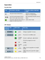
Page 21: ...nu item in the same menu level Decrements increments actual value Activates selected menu item or jumps to next menu level Loads actual value ESC OK Graphic LED display LED status Meaning green Voltage is applied to sensor green The sensor is in RUN mode Flashes green Sensor is waiting for adjustment The sensor signals an error red in RUN Flashes red in STOP yellow Object was recognized as a taugh...

Page 22: ...E00749101 01 Start up Overview of the steps in commissioning Requirements for commissioning The SIMATIC MV230 is mounted and connected 24 V DC Commissioning steps 1 Carry out basic settings Setting 2 Train model s Train 3 Test adjustments Test 4 Activate test mode Run ...

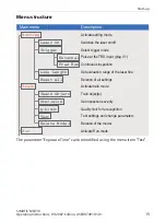
Page 23: ...6ZLWFKHV WKH ODVHU RQ RII 3XOVH DW WKH 75 LQSXW SOXJ 7UDLQ REMHFW V FWLYDWH WUDLQ PRGH FWLYDWH VHWWLQJ PRGH 6HW LQVSHFWLRQ VHYHULW 4XDOLW OLPLW IRU UHUHFRJQLWLRQ 7HVW VHWWLQJV DQG FKDQJH SDUDPHWHUV HOHWLRQ RI WKH PRGHO FWLYDWH 5XQ PRGH HOHWLRQ RI DOO VHWWLQJV RQWLQXRXV LQVSHFWLRQ 0DLQ PHQX HVFULSWLRQ Setting Precision Trigger Line Length Laser On Free Run External Reset All Q Limit Delete Model Te...

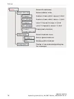
Page 24: ...W LQIR VXEPHQXV 1XPEHU RI WHVWV ZLWK 4 YDOXHV 4 OLPLW HOHWH UHVHW DOO HQWULHV 6HOHFW FKHFNVXP PHQX 6HQVRU JOREDO FKHFNVXP 0RGHO VSHFLILF FKHFNVXP LVSOD RI QRQ DFNQRZOHGJHG GLDJQRV WLFV PHVVDJHV LVW RI ORZHVW 4 YDOXHV ุ 4 OLPLW LVW RI KLJKHVW 4 YDOXHV 4 OLPLW Info Diagnosis Statistics Checksum OKcnt N_OKcnt Global XX__ OKmin N_OKmax Reset Statistics ...

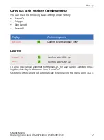
Page 25: ...ings under Setting Laser On Trigger Line Length Reset All Laser On To allow mechanical alignment of the sensor the laser can be switched on us ing the OK key in the menu item Laser On Switching off is carried out automatically when leaving the menu using OK RQILUP E SUHVVLQJ NH 2 LVSOD FWLRQ VHTXHQFH Setting RQILUP ZLWK 2 NH RQILUP ZLWK 2 NH Laser On Exit ...

Page 26: ...e time continuous Note In Free Run TRG functions as an enable input START STOP Tests are carried out continuously as long as a logical 1 is present RQILUP E SUHVVLQJ NH 2 UDQFK WR UHH 5XQ XVLQJ WKH DUURZ NH V RQILUP E SUHVVLQJ NH 2 RQILUP E SUHVVLQJ NH 2 RU Trigger Free Run External 5HVXOW 5HVXOW 5HVXOW 75 2 1B2 W F F W GHOD W RXW W WUJ W SURF 5HVXOW W F F 75 2 1B2 5HVXOW W RXW W F F 5HVXOW ...

Page 27: ...widths are not detected by the sensor as a trig ger tdelay Response time max 16 ms tproc Processing time max 34 ms Image evaluation and capture tout Output signal 15 ms External The output signal is reset with a new trigger pulse The signal remains on for at least 15 ms Free Run At the end of the last test and TRG 0 the result is still present for 15 ms ...

Page 28: ...n range is 100 and can be minimized to 30 in steps of 10 The evaluation range always commences from the right with viewing direction onto display side of sensor up to the selected percent age value Note The sensitivity of the sensor is increased when the evaluation range is limited Note If the evaluation range is changed for models which have already been trained these should be trained again and ...

Page 29: ... NH 2 Reset All Confirm RQILUP E SUHVVLQJ NH 2 6HOHFW PRGHO QXPEHU RQILUP E SUHVVLQJ NH 2 FWLRQ VHTXHQFH LVSOD Model No XX_ _ Train ESC ESC 7UDLQLQJ D PRGHO 5HWXUQ WR PHQX PRGHO 1R BB 3RVLWLRQ PRGHO REMHFW DSWXUH LPDJH ZLWK 2 NH DOVR SRVVLEOH YLD WULJJHU LQSXW 3LQ RI 0 VRFNHW 6DYH ZLWK 2 NH 6 NH WR UHWXUQ ZLWKRXW VDYLQJ WR GLVSOD PRGHO 1R BB GHIDXOW FXUUHQW PRGHO 1R OK Trigger ESC End Begin teach ...

Page 30: ...cted model number is not yet used XXP_ The selected model number is already used by a model Teach Train model s The object to be tested must remain stationary underneath the sensor during the train procedure LVSOD FWLRQ VHTXHQFH 6HW TXDOLW OLPLW RQILUP E SUHVVLQJ NH 2 KDQJH FRQIRUPDQFH YDOXH 0RGHO VXFFHVVIXOO WDXJKW 7KH VHQVRU LV UHDG IRU VWHS 7HVW VHWWLQJV Q limit XX Complete ESC FWLYDWH WHVW R W...

Page 31: ...Through selection in the Training menu The tolerance bandwidth and inspection precision are directly dependent on one another Note The sensitivity to ambient light is increased when Precision High is selected In such a case make sure that the lighting conditions in the environ ment of the sensor remain constant Precision Tolerance band Inspection precision Low Large 3 mm Coarse Changes in the heig...

Page 32: ...pares the height profile of the tested object with that of the trained object and determines the correlation percentage Calculated value Q limit Object has been recognized switching output OK is set OK LED is lit Calculated value Q limit Object has not been recognized switching output N_OK is set OK LED is lit Value range Q limit 0 to 99 default setting 80 ...

Page 33: ...H SDUDPHWHUV E SUHVVLQJ NH 2 QG WHVW E SUHVVLQJ NH 6 7HDFKLQJ SURFHVV FRPSOHWHG UDQFK WR 5XQ PRGH 5HFRUG LPDJH E SUHVVLQJ NH 2 DOVR SRVVLEOH YLD WULJJHU LQSXW 3LQ RI WKH 0 VRFNHW 6LJQDO WR V ุ 4 OLPLW 2 OLJKWV XS 4 OLPLW 1B2 OLJKWV XS 5HSHDW XQWLO WKH UHTXLUHG LPDJHV KDYH EHHQ FKHFNHG QG WHVW E SUHVVLQJ NH 6 RQIRUPDQFH YDOXH OK Trigger ESC End XX OK Trigger Change Parameters OK ESC Begin Test Teac...

Page 34: ...sure time is determined by the sensor However it can also be sent individually With mixed materials e g dark absorbing and bright reflecting surfaces the exposure can therefore be manually adapted to the material relevant to the task The exposure values must be set higher in the case of dark or absorbing mate rials and lower with bright or reflecting materials The object must be trained again if t...

Page 35: ...ia the arrow keys ESC ESC RQILUP E SUHVVLQJ NH 2 LVSOD RI WKH PRGHO QXPEHU VHOHFWHG YLD 6 LQSXWV 6HQVRU UHDG IRU LQVSHFWLRQ WULJJHUHG YLD 75 FWLRQ VHTXHQFH LVSOD RQIRUPDQFH YDOXH 6LJQDO WR V ุ 4 OLPLW 2 OLJKWV XS 4 OLPLW 1B2 OLJKWV XS QG 5XQ PRGH E SUHVVLQJ NH 6 H 2 6WRS 5XQ PRGH UDQFK WR PDLQ PHQX 5HWXUQ WR 5XQ PRGH E SUHVVLQJ NH 6 Run XXP _ XX Stop OK ESC ...

Page 36: ...puts The chart shows a change in model from No 10 to No 12 Result Result 6 5 75 2 1B2 W 6 W 5 Result Result tSEL Changeover time max 30 ms A stable input signal status must be applied to the SEL bits within 30 ms to ensure that model changeover can be performed suc cessfully tRDY Changeover time max 200 ms After 200 ms the sensor is ready for inspection ...

Page 37: ... when the power supply is switched off Parameters Description Purpose OKcnt Number of tests with Q value Q limit Values are calcula ted for all measure ments in Run and can be deleted using Reset Statis tics Checking of pro duction with sen sor already set up N_OKcnt Number of tests with Q value Q limit OKmin List of 10 lowest Q values Q limit Values only apply to the last model created in Run and...

Page 38: ...al checksum is the value which results from all model specific and glo bal settings It can be scanned from Run mode using the arrow keys even with key disabling activated Model specific checksum A checksum is saved for each trained model which results from the individual parameters of the respective model Diagnosis The non acknowledged diagnostics messages are displayed in Diagnosis Note Modificat...

Page 39: ...t is present or was present and that the result is invalid The DIAG bit is set for at least 20 ms and is reset by the sensor as soon as the fault is no longer present The sensor indicates on its display the currently active or unacknowledged er rors with their error codes The display starts with the most recent error Indi cated error messages are deleted when the error has been rectified and are a...

Page 40: ...Incorrect working distance Check the working distance Exposure time too short Increase the exposure time Failure of laser shadow in laser projection Check the laser function or replace the sensor Dirt deposits Eliminate deposits E05 Less than 50 of the laser line have been detected Multiple reflec tions test object too dark Vary sensor align ment High ambient light Provide shade E06 Saving the sen...

Page 41: ...tage too low Power supply too low Check power sup ply Overload at digi tal outputs Eliminate overload E10 Invalid trigger Triggering when sen sor is not ready Note cycle time ensure triggering is correct min 50 ms E11 Internal error Temporary failure fault EMC overheat ing Check the environ mental condition FaEr HW defect in indi vidual compo nents sequential program cannot be executed Sensor spec...

Page 42: ...Mechanical loading acc to IEC 61131 2 Vibrational load during operation 10 to 58 Hz 58 to 150 Hz 0 075 mm 9 8 m s2 Shock load during operation 150 m s2 Voltages currents potentials Supply voltage L 20 4 V 28 8 V DC including ripple with reverse polarity protection Nominal value 24 V Rated current 1 A Electrical isolation None Data for inputs Rated voltage 24 V Input current 7 mA typical Voltage ra...

Page 43: ...5 1 EN 60825 1 Image capture and evaluation Image sensor CMOS sensor 750 x 480 pixels Response time Max 16 ms Cycle time Max 50 ms Length of laser line 50 to 75 mm Operating range 210 to 310 mm Principle of measurement Split beam laser based triangulation Test type Profile evaluation Accuracy physical resolution Height accuracy 0 5 mm Width accuracy 0 2 mm Triggering for image capture External ext...

Page 44: ...6 EEC Electromagnetic Compatibility EMC guideline The EU conformity certificates are available for the relevant author ities and are kept at the following address Siemens AG Automation and Drives Factory Automation Sensors P O Box 4848 90437 NUREMBERG GERMANY EMC Directive SIMATIC MV230 is designed for industrial use Marks for Australia and New Zealand SIMATIC MV230 complies with the requirements ...

Page 45: ...49 0 180 5050 222 Fax 49 0 180 5050 223 Internet Visit our site on the Internet at http www siemens com automation service support You can send a support query to http www siemens com automation support request The online catalog and the online ordering system is available at www siemens com automation mall For further information on factory automation sensors visit http www siemens com simatic se...

Page 46: ...Dimensional drawing SIMATIC MV230 38 Operating Instructions 01 2007 Edition A5E00749101 01 Dimensional drawing 1RW VXLWDEOH IRU JURXQGLQJ OO 0 WKUHDGV Dimensions in mm ...

Page 47: ......

Page 48: ...Siemens AG Automation and Drives Factory Automation Sensors P O Box 4848 90437 NUREMBERG GERMANY www siemens com simatic sensors ...

Reviews: