background image

Mounting 


ANT793-8DP 

32


C79000-G8974-C320-02, 01/2017 

3.2


Mounting on rotating bracket 

3.2.1


Mounting the support on a rotating bracket 

Installation options 
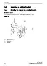
It is possible to mount the rotating bracket in two different positions: 
Option 1: 


  Rotating bracket 

  Support 

  Screws 

Summary of Contents for SIMATIC NET ANT793-8DP

Page 1: ......

Page 2: ......

Page 3: ...1 Deutsch 3 English 25 ...

Page 4: ......

Page 5: ...ng befähigt im Umgang mit diesen Produkten Systemen Risiken zu erkennen und mögliche Gefährdungen zu vermeiden Bestimmungsgemäßer Gebrauch von Siemens Produkten Beachten Sie Folgendes WARNUNG Siemens Produkte dürfen nur für die im Katalog und in der zugehörigen technischen Dokumentation vorgesehenen Einsatzfälle verwendet werden Falls Fremdprodukte und komponenten zum Einsatz kommen müssen diese v...

Page 6: ...entsprechenden Vorsichtsmaßnahmen nicht getroffen werden WARNUNG bedeutet dass Tod oder schwere Körperverletzung eintreten kann wenn die entsprechenden Vorsichtsmaßnahmen nicht getroffen werden VORSICHT bedeutet dass eine leichte Körperverletzung eintreten kann wenn die entsprechenden Vorsichtsmaßnahmen nicht getroffen werden ACHTUNG bedeutet dass Sachschaden eintreten kann wenn die entsprechenden...

Page 7: ...andmontage 8 3 2 Montage auf drehbarem Haltewinkel 10 3 2 1 Halterung an drehbaren Haltewinkel montieren 10 3 2 2 Wandmontage 12 3 2 3 Mastmontage 13 3 2 4 Antenne an Haltevorrichtung montieren 14 3 2 5 Antenne justieren 15 4 Anschließen 17 4 1 Hinweise zum Anschließen 17 4 2 Anschließen der Verbindungsleitung 17 5 Technische Daten 18 5 1 Technische Daten ANT793 8DP 18 6 Maßbilder 22 6 1 ANT793 8D...

Page 8: ... 62305 WARNUNG Das Gerät und dessen Bauteile darf nur entsprechend der im Katalog oder der Betriebsanleitung beschrieben Verwendung eingesetzt werden Es darf nur mit Geräten oder Komponenten anderer Hersteller kombiniert werden wenn diese Komponenten durch Siemens freigegeben wurden Die Anleitung ist für den industriellen Einsatz vorgesehen Eine korrekte und sichere Funktion des Geräts ist nur dan...

Page 9: ...t R SMA Anschlüssen z B SCALANCE W700 RJ45 ist die flexible Verbindungsleitung N Connect R SMA Male Male als Zubehör lieferbar Länge in m Artikelnummer 0 3 6XV1875 5CE30 1 6XV1875 5CH10 2 6XV1875 5CH20 5 6XV1875 5CH50 10 6XV1875 5CN10 Verbindungsleitung N Connect N Connect Zum Anschluss an einen SCALANCE W700 M12 mit N Connect oder zur Verbindung mit dem Blitzschutzelement LP798 1N LP798 2N ist di...

Page 10: ...793 8DP 8 C79000 G8974 C320 02 01 2017 3 Montage 3 1 Direkte Wandmontage Bohrbild Das folgende Bild zeigt den Abstand der Befestigungsbohrungen Verwenden Sie zum Bohren diese Angaben Die Maße sind in mm angegeben ...

Page 11: ...olgende Schritte durch um die Antenne an einer Wand zu montieren Hinweis Beachten Sie dass der Abstand zwischen Antenne und Wand mindestens 4 2 mm betragen muss 1 Bohren Sie Löcher Durchmesser 6 mm in die Wand und stecken Sie die Dübel in die Löcher 2 Positionieren Sie die Halterung und befestigen Sie sie mit Schrauben ...

Page 12: ...e an der Halterung und schieben Sie sie herunter bis die Antenne einrastet 3 2 Montage auf drehbarem Haltewinkel 3 2 1 Halterung an drehbaren Haltewinkel montieren Montagemöglichkeiten Es besteht die Möglichkeit den drehbaren Haltewinkel in zwei verschiedenen Positionen zu montieren ...

Page 13: ...Montage ANT793 8DP C79000 G8974 C320 02 01 2017 11 Möglichkeit 1 Drehbarer Haltewinkel Halterung Schrauben Möglichkeit 2 Drehbarer Haltewinkel Halterung Schrauben ...

Page 14: ...ie abgebildet 3 2 2 Wandmontage Übersicht Bohrlöcher Dübel Drehbarer Haltewinkel Schrauben Halterung Vorgehen 1 Bohren Sie zwei Löcher Durchmesser 6 mm Der Abstand der Bohrlöcher beträgt 24 mm 2 Stecken Sie die Dübel in die Bohrlöcher 3 Positionieren Sie den drehbaren Haltewinkel an der Wand und schrauben Sie ihn fest ...

Page 15: ...montage Übersicht Mast Schlauchklemmen Hinweis Die Befestigungselemente sind für einen Mastdurchmesser von 25 mm bis 85 mm geeignet Vorgehen Montieren Sie den drehbaren Haltewinkel mit zwei Schlauchklemmen an den Mast wie abgebildet Das Anzugsmoment beträgt 5 Nm ...

Page 16: ... G8974 C320 02 01 2017 3 2 4 Antenne an Haltevorrichtung montieren Übersicht Vorgehen 1 Setzen Sie die Antenne an die Halterung die an dem drehbaren Haltewinkel montiert ist 2 Schieben Sie die Antenne nach unten bis sie einrastet ...

Page 17: ...Montage ANT793 8DP C79000 G8974 C320 02 01 2017 15 3 2 5 Antenne justieren Übersicht Horizontale Achse Vertikale Achse ...

Page 18: ... Ausrichtung Vorgehen Hinweis Stellen Sie den drehbaren Haltewinkel nur im gelösten Zustand ein 1 Positionieren Sie die Antenne wie gewünscht 2 Ziehen Sie zuerst die Schraube für die vertikale Achse an Das Anzugsmoment beträgt 3 5 Nm 3 Ziehen Sie die Schraube für die horizontale Achse an Das Anzugsmoment beträgt 3 5 Nm ...

Page 19: ... 6GK5798 2LP10 2AA6 Hinweis Es wird empfohlen das wartungsfreie Blitzschutzelement LP798 2N zu verwenden Ausnahme Über die Antennenleitung erfolgt auch eine DC Speisung In diesem Fall kann nur das Blitzschutzelement LP798 1N verwendet werden WARNUNG Lebensgefahr durch Blitzschlag Der Einbau des genannten Blitzschutzelements zwischen einer Antenne und einem SCALANCE W700 stellt noch keinen ausreich...

Page 20: ...0 MHz 4940 5350 MHz Antennengewinn 13 dBi 13 5 dBi Horizontaler Strahlungswinkel 40 40 Vertikaler Strahlungswinkel 35 35 Impedanz 50 Ω 50 Ω Polarisation Vertikal Stehwellenverhältnis VSWR 1 5 1 5 Zulässige Umgebungsbedingungen Umgebungstemperatur Während des Betriebs 40 C 80 C Während der Lagerung 40 C 80 C Während des Transports 40 C 80 C Bauform Maße und Gewicht Anschluss 1 x N Connector female ...

Page 21: ...Gewicht 110 g Abmessungen H x B x T Antenne 100 x 81 x 35 mm Drehbarer Haltewinkel 57 5 x 48 x 41 5 mm Halterung für Wandmontage 42 x 48 x 5 mm Zulassung Das Produkt ANT793 8DP verfügt über die folgenden Zulassungen EN50155 EN45545 2 DIN 5510 2 5 2 2 BS6853 NF F16 101 NF F16 102 ...

Page 22: ...Technische Daten ANT793 8DP 20 C79000 G8974 C320 02 01 2017 Horizontales Felddiagramm 4950 MHz Bild 5 1 Amplitude dB Azimuth deg ...

Page 23: ...Technische Daten ANT793 8DP C79000 G8974 C320 02 01 2017 21 Vertikales Felddiagramm 4950 MHz Bild 5 2 Amplitude dB Elevation deg ...

Page 24: ...Maßbilder ANT793 8DP 22 C79000 G8974 C320 02 01 2017 6 Maßbilder 6 1 ANT793 8DP Halterung Haltewinkel Seitenansicht Vorderansicht Die Maße sind in mm angegeben ...

Page 25: ...Maßbilder ANT793 8DP C79000 G8974 C320 02 01 2017 23 Halterung Vorderansicht Die Maße sind in mm angegeben ...

Page 26: ...en Benutzung durch Dritte für deren Zwecke die Rechte der Inhaber verletzen kann Haftungsausschluss Wir haben den Inhalt der Druckschrift auf Übereinstimmung mit der beschriebenen Hard und Software geprüft Dennoch können Abweichungen nicht ausgeschlossen werden so dass wir für die vollständige Übereinstimmung keine Gewähr übernehmen Die Angaben in dieser Druckschrift werden regelmäßig überprüft no...

Page 27: ... are capable of identifying risks and avoiding potential hazards when working with these products systems Proper use of Siemens products Note the following WARNING Siemens products may only be used for the applications described in the catalog and in the relevant technical documentation If products and components from other manufacturers are used these must be recommended or approved by Siemens Pr...

Page 28: ...of danger DANGER indicates that death or severe personal injury will result if proper precautions are not taken WARNING indicates that death or severe personal injury may result if proper precautions are not taken CAUTION indicates that minor personal injury can result if proper precautions are not taken NOTICE indicates that property damage can result if proper precautions are not taken If more t...

Page 29: ... wall mounting 29 3 2 Mounting on rotating bracket 32 3 2 1 Mounting the support on a rotating bracket 32 3 2 2 Wall mounting 34 3 2 3 Mast mounting 35 3 2 4 Mounting the antenna on the support 36 3 2 5 Adjusting the antenna 37 4 Connection 39 4 1 Notes on connecting up 39 4 2 Connecting the cables 40 5 Technical data 40 5 1 Technical specifications ANT793 8DP 40 6 Dimension drawings 43 6 1 ANT793...

Page 30: ...vices or components of other manufacturers that have been approved and released by Siemens These instructions are intended for industrial applications Correct and safe operation of the device is guaranteed only when it is transported stored set up installed used and maintained according to the recommendations 2 Description 2 1 Introduction Antenna characteristics The ANT793 8DP antenna is a direct...

Page 31: ...le For connection to a SCALANCE W700 M12 with N Connect or for connecting the lightning protection element LP798 1N LP798 2N the flexible connecting cable N Connect N Connect Male Male can be supplied as an accessory Length in m Article number 1 6XV1875 5AH10 2 6XV1875 5AH20 5 6XV1875 5AH50 10 6XV1875 5AN10 There is a control cabinet feedthrough available for IWLAN devices located in a control cab...

Page 32: ...Mounting ANT793 8DP 30 C79000 G8974 C320 02 01 2017 Overview Drilled holes Plugs Support Screws ...

Page 33: ...a wall Note Remember that the distance between the antenna and the wall must be at least 4 2 mm 1 Drill the holes in the wall diameter 6 mm and insert the plugs in the holes 2 Position the support and secure it with the screws 3 Place the antenna on the support and push it down until the antenna locks in place ...

Page 34: ...74 C320 02 01 2017 3 2 Mounting on rotating bracket 3 2 1 Mounting the support on a rotating bracket Installation options It is possible to mount the rotating bracket in two different positions Option 1 Rotating bracket Support Screws ...

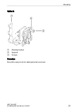
Page 35: ...Mounting ANT793 8DP C79000 G8974 C320 02 01 2017 33 Option 2 Rotating bracket Support Screws Procedure Mount the support on the rotating bracket as shown ...

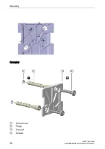
Page 36: ... mounting Overview Drilled holes Plugs Rotating bracket Screws Support Procedure 1 Drill two holes diameter 6 mm The distance between the drilled holes is 24 mm 2 Insert the plugs in the holes 3 Place the rotating bracket on the wall and secure it with the screws ...

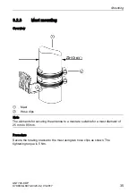
Page 37: ...2 3 Mast mounting Overview Mast Hose clips Note The elements for securing the antenna to a mast are suitable for a mast diameter of 25 mm to 85 mm Procedure Secure the rotating bracket to the mast using two hose clips as shown The tightening torque is 5 Nm ...

Page 38: ...93 8DP 36 C79000 G8974 C320 02 01 2017 3 2 4 Mounting the antenna on the support Overview Procedure 1 Place the antenna on the support secured to the rotating bracket 2 Push the antenna down until it locks in place ...

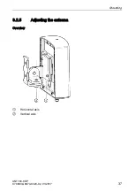
Page 39: ...Mounting ANT793 8DP C79000 G8974 C320 02 01 2017 37 3 2 5 Adjusting the antenna Overview Horizontal axis Vertical axis ...

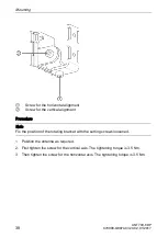
Page 40: ...vertical alignment Procedure Note Fix the position of the rotating bracket with the setting screws loosened 1 Position the antenna as required 2 First tighten the screw for the vertical axis The tightening torque is 3 5 Nm 3 Then tighten the screw for the horizontal axis The tightening torque is 3 5 Nm ...

Page 41: ...ories of SIMATIC NET Industrial WLAN Lightning protection element LP798 1N article number 6GK5798 2LP00 2AA6 Lightning protection element LP798 2N article number 6GK5798 2LP10 2AA6 Note We recommend that you use the maintenance free lightning protector LP798 2N Exception When there is also DC power is supplied via the antenna cable In this case only the lightning protector LP798 1N can be used WAR...

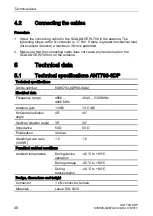
Page 42: ...0 nor on the antenna 5 Technical data 5 1 Technical specifications ANT793 8DP Technical specifications Article number 6GK5793 8DP00 0AA0 Electrical data Frequency range 4900 4940 MHz 4940 5350 MHz Antenna gain 13 dBi 13 5 dBi Horizontal radiation angle 40 40 Vertical radiation angle 35 35 Impedance 50 Ω 50 Ω Polarization Vertical Standing wave ratio VSWR 1 5 1 5 Permitted ambient conditions Ambien...

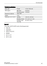
Page 43: ...aximum 220 km h During operation 160 km h Degree of protection IP66 IP67 Weight 110 g Dimensions H x W x D Antenna 100 x 81 x 35 mm Rotating bracket 57 5 x 48 x 41 5 mm Holder for wall mounting 42 x 48 x 5 mm Approval The product ANT793 8DP has the following approvals EN50155 EN45545 2 DIN 5510 2 5 2 2 BS6853 NF F16 101 NF F16 102 ...

Page 44: ...Technical data ANT793 8DP 42 C79000 G8974 C320 02 01 2017 Horizontal radiation pattern 4950 MHz Figure 5 1 Amplitude dB azimuth deg ...

Page 45: ...Dimension drawings ANT793 8DP C79000 G8974 C320 02 01 2017 43 Vertical radiation pattern 4950 MHz Figure 5 2 Amplitude dB elevation deg 6 Dimension drawings ...

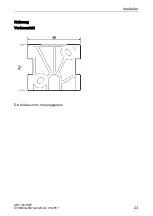
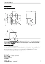
Page 46: ...Dimension drawings ANT793 8DP 44 C79000 G8974 C320 02 01 2017 6 1 ANT793 8DP mounting bracket Side view front view The dimensions are specified in mm ...

Page 47: ...Dimension drawings ANT793 8DP C79000 G8974 C320 02 01 2017 45 Support Front view The dimensions are specified in mm ...

Page 48: ...se use by third parties for their own purposes could violate the rights of the owner Disclaimer of Liability We have reviewed the contents of this publication to ensure consistency with the hardware and software described Since variance cannot be precluded entirely we cannot guarantee full consistency However the information in this publication is reviewed regularly and any necessary corrections a...

Reviews: