Description of the device
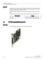
1.1 CP 1604 communications processor
CP 1604 / CP 1616
18
Operating Instructions, 02/2017, C70000-G8976-C218-08
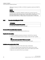
WARNING
Do not connect pins 3 to 9!
Do not connect pins 3 to 9! Otherwise the CP may be destroyed.
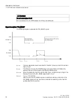
Signal description "PE_WAKE"
The following diagram represents the "PE_WAKE" signal:
t
pci_reset
The host application shuts down the PC. The RST_N level on the PCI bus then
falls to "Low".
t
pe_wake
The firmware receives the PROFIenergy end pause frame and initiates the
startup procedure of the host PC with the PE_WAKE signal.
t
pci_unreset
When it restarts, the host PC pulls the RST_N pin on the PCI bus to "High". The
firmware then sets the PE_WAKE signal back to "Low".
t
undefined
t
undefined
= 12 seconds
After PC start, the PE_WAKE signal is not defined until this point in time. The
PE_WAKE signal can only be used as controller for switching on the host PC
system after the 12 seconds.

