background image

Montageanleitung für / Assembly Instructions for IE RJ45 Plug PRO (6GK1901-1BB10-6AA0) 
 

Copyright © 2010 Siemens AG  
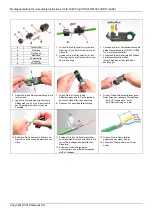
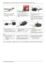


a Forcing 

nut 

b Sealing 

ring 

c Rear 

wall 

d Latch 
e Contact 

holder 

f Housing 

g Metal 

foil 


1.  Release the forcing nut (a) and sealing 

ring (b) from the rear wall (c) of the plug.  

2.  Push the forcing nut (a), the sealing ring 

(b) and the back wall (c) loosely over the 
cable. 

3.  Use the yellow knife cassette 

6GK1901-1GB00 (12 mm knife clearance) 
in the stripping tool! 

4.  When necessary, adjust the cutting depth 

of the knife cassette with the socket-head 
screws at the head end of the tool! 


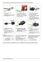
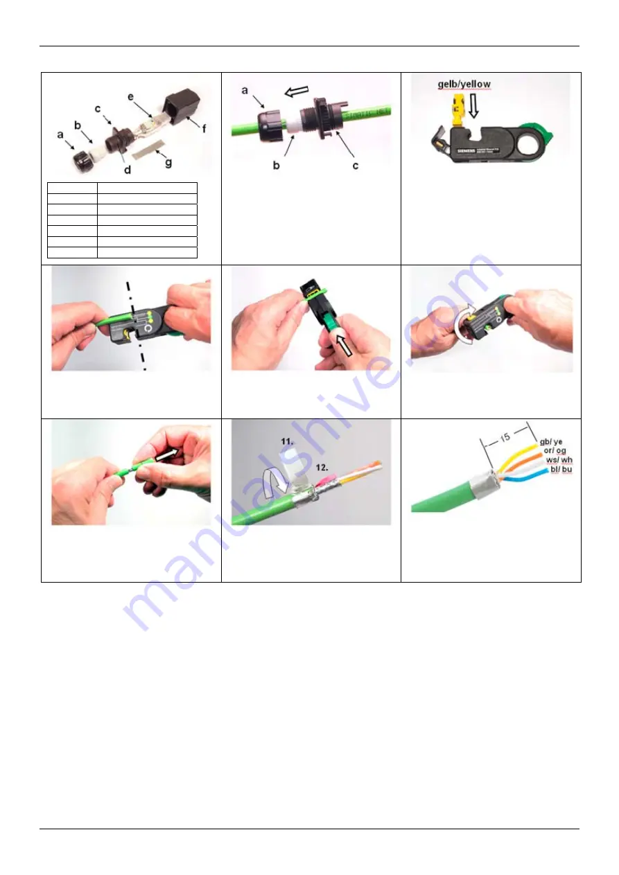
5.  Take the stripping tool in your right hand. 
6.  Place the cable on the shortest stripping 

setting (approx. 30 mm). Use your left 
index finger as the limit stop. 

7.  Fit the cable in the stripping tool. Your left 

index finger is the limit stop. 

8.  Tighten the stripping tool. 

9.  To strip the insulation, turn the tool in the 

direction of the arrow 
  - approx. 4 times for PVC insulation 
  - approx. 8 times for PUR insulation. 


10. Pull of the cable jacket, shield and the 

white filler with your hand. 

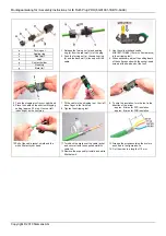
11. Turn back the braid over the cable jacket 

and secure it with the supplied metallic 
cable foil. 

12. Remove the exposed foil shield and white 

filler below it. 

13. Arrange the wires according their colors 

as shown in the figure above. 

14.  Cut the wires to a length of 15 mm. 

Summary of Contents for SIMATIC NET IE RJ45 Plug PRO

Page 1: ...6XV1870 2F IE FC ITP Marine Cable 2x2 6XV1840 4AH10 IE FC Food Cable 2x2 6XV1871 2L IE FC Festoon Cable 2x2 6XV1871 2S UL CSA conditions Wire size AWG 22 solid wire only Max Voltage 50 V Max Amperes 1 75 A CAUTION NOT FOR INTERRUPTING CURRENT ATTENTION NE PAS UTILISER POUR COUPER LE COURANT Nachfolgend finden Sie Informationen in deutscher Sprache Die aktuellsten Hinweise finden Sie unter folgende...

Page 2: ... Personals Qualifiziertes Personal im Sinne dieser Betriebsanleitung bzw der Warnhinweise sind Personen die mit Aufstellung Montage Inbetriebsetzung und Betrieb dieses Produktes vertraut sind und über die ihrer Tätigkeit entsprechenden Qualifikation verfügen und in erster Hilfe geschult sind __________________________________________________________________________________________ We have checked ...

Page 3: ... die rechte Hand 6 Legen Sie die Leitung an das kürzeste Ablängmaß ca 30 mm Benutzen Sie den Zeigefinger der linken Hand als Anschlag 7 Legen Sie die Leitung in das Abisolierwerkzeug ein Der Zeigefinger der linken Hand bildet den Anschlag 8 Spannen Sie das Abisolierwerkzeug 9 Drehen Sie das Abisolierwerkzeug zum Abisolieren der Leitung in Pfeilrichtung bei PVC Isolierung ca 4 mal bei PUR Isolierun...

Page 4: ...e Beschriftung des Gehäuses 24 Drücken Sie die Rückwand in das Gehäuse bis es hörbar einrastet Vermeiden Sie hierbei mögliche Verpressungen der um die Rückwand laufenden Dichtung 25 Drehen Sie die Druckmutter fest zu Stecker öffnen 1 Zum Öffnen des Steckers hebeln Sie die Rastfeder im Gehäuse mit einem Schlitzschraubendreher in Richtung Seitenwand 2 Ziehen Sie die Rückwand bei herunter gehaltenem ...

Page 5: ...ad end of the tool 5 Take the stripping tool in your right hand 6 Place the cable on the shortest stripping setting approx 30 mm Use your left index finger as the limit stop 7 Fit the cable in the stripping tool Your left index finger is the limit stop 8 Tighten the stripping tool 9 To strip the insulation turn the tool in the direction of the arrow approx 4 times for PVC insulation approx 8 times...

Page 6: ...e same side as the labeling of the housing 24 Press the rear wall into the housing until it clicks into place audibly Avoid pressing on the seal around the rear wall 25 Tighten the forcing nut completely Opening the plug 1 To open the plug lever the catch in the housing towards the side wall with a slotted screwdriver 2 Pull the rear wall out of the housing by the cable while holding down the scre...

Reviews: