background image


Description of the device 


2.4 Terminals 

SCALANCE M826 
Operating Instructions, 08/2018, C79000-G8976-C362-05 

23


2.4


Terminals 

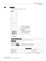
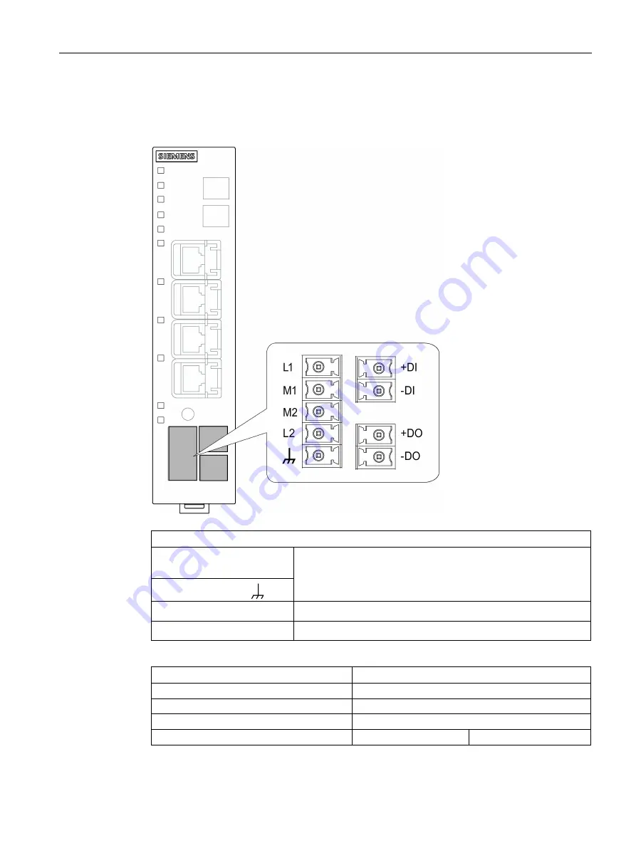
The device has the following terminal strips. 


Connectors and terminal markings 

 Input for the power supply 

L1, M2, L2, M2 

Terminal strip with five screw connectors 
 

 Functional ground 


 Digital input +DI, -DI 

Terminal strip with two screw connectors 

 Digital DO, -DO 

Terminal strip with two screw connectors 


Terminals 

 - 


Screwdriver blade 

 0.4 x 2.5 (DIN 5264) 

Clamping screw 

M2 

Tightening torque 

0.2 Nm - 0.25 Nm 

AWG 

28 AWG 

16 AWG 

Summary of Contents for SIMATIC NET SCALANCE M826

Page 1: ...tion Remote Networks SCALANCE M826 Operating Instructions 08 2018 C79000 G8976 C362 05 Preface Security recommendations 1 Description of the device 2 Installation 3 Connecting up 4 Dimension drawings 5 Technical specifications 6 Approvals A ...

Page 2: ...ion may be operated only by personnel qualified for the specific task in accordance with the relevant documentation in particular its warning notices and safety instructions Qualified personnel are those who based on their training and experience are capable of identifying risks and avoiding potential hazards when working with these products systems Proper use of Siemens products Note the followin...

Page 3: ...M826 Further documentation System manual Industrial Ethernet The system manual contains information on other SIMATIC NET products that you can operate along with the devices of this product line in an Industrial Ethernet network There you will find among other things optical performance data of the communications partner that you require for the installation The SIMATIC NET Industrial Ethernet sys...

Page 4: ...ing settings tab Entry list Entry type Manuals You will find the documentation for the SIMATIC NET products relevant here on the data medium that ships with some products Product CD product DVD SIMATIC NET Manual Collection You will find the article numbers for the Siemens products of relevance here in the following catalogs SIMATIC NET Industrial Communication Industrial Identification catalog IK...

Page 5: ...ecurity Siemens products and solutions undergo continuous development to make them more secure Siemens strongly recommends that product updates are applied as soon as they are available and that the latest product versions are used Use of product versions that are no longer supported and failure to apply the latest updates may increase customers exposure to cyber threats To stay informed about pro...

Page 6: ...nse conditions in the following documents on the supplied data medium M87x M81x M826 OSS_Scalance M 800 S615_86 pdf M804PB OSS_Scalance M 804_86 pdf SIMATIC NET glossary Explanations of many of the specialist terms used in this documentation can be found in the SIMATIC NET glossary You will find the SIMATIC NET glossary on the Internet at the following address 50305045 https support industry sieme...

Page 7: ...Preface SCALANCE M826 Operating Instructions 08 2018 C79000 G8976 C362 05 7 ...

Page 8: ......

Page 9: ...all mounting 31 3 3 Installing on the DIN rail 32 3 4 Installing on the S7 300 standard rail 33 3 5 Installing on the S7 1500 standard rail 34 3 6 Mounting on a pedestal 35 4 Connecting up 39 4 1 Safety when connecting up 39 4 2 Grounding 41 4 3 Digital input output 42 4 4 Power supply 45 4 5 DSL connection 47 4 6 Ethernet port 52 4 7 Replacing the PLUG 53 5 Dimension drawings 57 5 1 SCALANCE M826...

Page 10: ...08 2018 C79000 G8976 C362 05 A 2 3 RoHS 66 A 3 General approvals 67 A 3 1 ATEX 67 A 3 2 IECEx 69 A 3 3 RCM C TICK 70 A 3 4 FM certification 70 A 3 5 UL certification product safety 70 A 3 6 UL HAZ LOC certification explosion protection 71 A 3 7 EAC 71 Index 73 ...

Page 11: ...orts on the device Unused ports can be used to gain forbidden access to the plant Software security functions Keep the software up to date Check regularly for security updates of the product You will find information on this on the Internet pages Industrial Security https www siemens com industrialsecurity Inform yourself regularly about security advisories and bulletins published by Siemens Produ...

Page 12: ...d certificates you require to set up TLS VPN IPsec OpenVPN and SINEMA RC The device contains a pre installed X 509 certificate with key Replace this certificate with a self made certificate with key We recommend that you use a certificate signed by a reliable external or internal certification authority Use the certification authority including key revocation and management to sign the certificate...

Page 13: ... Check whether use of SNMPv1 is necessary SNMPv1 is classified as non secure Use the option of preventing write access The product provides you with suitable setting options If SNMP is enabled change the community names If no unrestricted access is necessary restrict access with SNMP HTTP HTTPS Telnet SSH TFTP SFTP Use secure protocols when access to the device is not prevented by physical protect...

Page 14: ...e port when the port is accessed via a local connection e g via LAN External access Default port status of the port when the port is accessed via an external connection e g WAN WLAN VPN Authentication Specifies whether or not the protocol is authenticated during access Encryption Specifies whether the transfer is encrypted Protocol Protocol port number Port status Default port status Authenticatio...

Page 15: ... server UDP 123 Open Closed Closed No No Siemens Remote Service cRSP SRS TCP 443 Open only outgoing Closed Closed Yes Yes PROFINET UDP 34964 Open Open Open No No OpenVPN to SINEMA RC TCP UDP depending on server config only with Key Plug Open only outgoing Closed Closed Yes Yes TFTP UDP 69 Open only outgoing Closed Closed No No DynDNS TCP 80 Open only outgoing Closed Closed No No Telnet TCP 23 Open...

Page 16: ...Security recommendations SCALANCE M826 16 Operating Instructions 08 2018 C79000 G8976 C362 05 ...

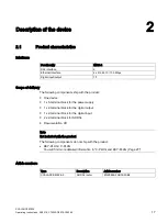
Page 17: ... ship with the product One device 1 x 5 terminal block for the power supply 1 x 2 terminal block for the digital output 1 x 2 terminal block for the digital input 2 x 2 terminal block for SHDSL Documentation CD Note Not included with the product The following components do not ship with the product KEY PLUG C PLUG You will find more detailed information in C PLUG and KEY PLUG Page 27 Article numbe...

Page 18: ...t show evidence of damage If you use damaged parts there is no guarantee that the device will function according to the specification If you use damaged parts this can lead to the following problems Injury to persons Loss of the approvals Violation of the EMC regulations Use only undamaged parts 1 Make sure that the package is complete 2 Check all the parts for transport damage ...

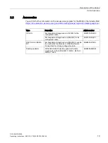
Page 19: ...language en Type Properties Article number C PLUG Exchangeable storage medium 32 MB for the configuration data 6GK1900 0AB00 Exchangeable storage medium 256 MB for the configuration data 6GK1900 0AB10 KEY PLUG SINEMA RC Exchangeable storage medium 256 MB to enable the connection functionality to SINEMA Remote Connect and for storing configuration data 6GK5908 0PB00 Desktop pedestal SCALANCE M 800 ...

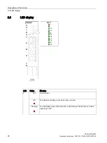
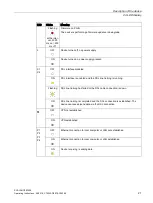
Page 20: ...erating Instructions 08 2018 C79000 G8976 C362 05 2 3 LED display LED Status Meaning F OFF No fault error ON The device is starting up or an error has occurred Flashing The bootloader waits in this status for a new firmware file that you can down load using TFTP ...

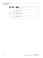
Page 21: ...ly present X1 X2 OFF DSL interface disabled ON DSL interface is enabled and the DSL line training is running Flashing DSL line training has failed or the DSL cable connection is down ON DSL line training is completed and the DSL connection is established The device can receive send data via the DSL connection OFF VPN not established ON VPN established P1 P2 P3 P4 OFF Ethernet connection to local c...

Page 22: ...device 2 3 LED display SCALANCE M826 22 Operating Instructions 08 2018 C79000 G8976 C362 05 LED Status Meaning DI OFF Digital input inactive ON Digital input active DO OFF Digital output inactive ON Digital output active ...

Page 23: ...Connectors and terminal markings Input for the power supply L1 M2 L2 M2 Terminal strip with five screw connectors Functional ground Digital input DI DI Terminal strip with two screw connectors Digital output DO DO Terminal strip with two screw connectors Terminals Screwdriver blade 0 4 x 2 5 DIN 5264 Clamping screw M2 Tightening torque 0 2 Nm 0 25 Nm AWG 28 AWG 16 AWG ...

Page 24: ...CALANCE M826 24 Operating Instructions 08 2018 C79000 G8976 C362 05 Terminals Wire end ferrule without plastic collar to DIN 46228 1 0 2 mm2 1 5 mm2 Wire end ferrule with plastic collar to DIN 46228 4 0 2 mm2 1 5 mm2 Stripped length 7 mm 7 mm ...

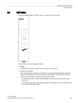
Page 25: ...an 3 seconds to run a restart Loading new firmware If the normal procedure with the Load Save menu of Web Based Management does not work the SET button can be used to load new firmware This situation can occur if there is a power outage during the normal firmware update Hold down the button until the red fault LED F starts to flash after approximately 3 seconds Now release the button The bootloade...

Page 26: ...manently lit Now release the button and wait until the fault LED F goes off again The device then starts automatically with the factory settings By resetting to the factory configuration settings the device loses its configured IP address Since the device does not have a configured IP address you need to assign an IP address e g via a DHCP server or using the Primary Setup Tool You will find more ...

Page 27: ... DHCP and the DHCP server has not been reconfigured accordingly A reconfiguration is necessary if you use functions based on MAC addresses If an incorrect PLUG for example from another product or a damaged PLUG is inserted the device signals an error with the F LED You can either remove the PLUG again or select the option to reformat the PLUG In terms of the PLUG devices work in two modes Without ...

Page 28: ......

Page 29: ...ware of the reason for restricted access and the required safety measures at an ambient temperature higher than 50 C Safety notices on use in hazardous areas General safety notices relating to protection against explosion WARNING When used in hazardous environments corresponding to Class I Division 2 or Class I Zone 2 the device must be installed in a cabinet or a suitable enclosure General notes ...

Page 30: ...or the cables Regardless of the type of installation make sure that there is suitable strain relief for the connecting cable Shielding of cables If cables are installed permanently it is advisable to remove the insulation of the shielded cable and to establish contact on the shield PE conductor bar Permitted installation direction Vertical installation ventilation openings at the top and bottom Ke...

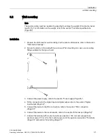
Page 31: ...he wall with two screws When mounting on a wall use mounting fittings suitable for the type of wall 3 Connect the power supply refer to the section Power supply Page 45 4 Fit the connectors for the digital input and digital output refer to the section Digital input output Page 42 5 Connect the device to the DSL connection refer to the section DSL connection Page 47 6 Connect the device to the loca...

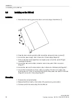
Page 32: ...put and digital output refer to the section Digital input output Page 42 5 Connect the device to the DSL connection refer to the section DSL connection Page 47 6 Connect the device to the local network refer to the section Ethernet port Page 52 7 Connect the terminal with as short a cable as possible 150 mm and a large cross sectional area of 1 5 mm to the functional ground of the system see secti...

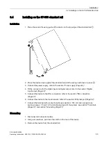
Page 33: ...connectors for the digital input and digital output refer to the section Digital input output Page 42 5 Connect the device to the DSL connection refer to the section DSL connection Page 47 6 Connect the device to the local network refer to the section Ethernet port Page 52 7 Connect the terminal with as short a cable as possible 150 mm and a large cross sectional area 1 5 mm to the functional grou...

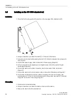
Page 34: ... section Power supply Page 45 5 Fit the connectors for the digital input and digital output refer to the section Digital input output Page 42 6 Connect the device to the DSL connection refer to the section DSL connection Page 47 7 Connect the device to the local network refer to the section Ethernet port Page 52 8 Connect the terminal with as short a cable as possible 150 mm and a large cross sect...

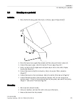
Page 35: ...digital input and digital output refer to the section Digital input output Page 42 5 Connect the device to the DSL connection refer to the section DSL connection Page 47 6 Connect the device to the local network refer to the section Ethernet port Page 52 7 Connect the terminal with as short a cable as possible 150 mm and a large cross sectional area 1 5 mm to the functional ground of the system se...

Page 36: ...Installation 3 6 Mounting on a pedestal SCALANCE M826 36 Operating Instructions 08 2018 C79000 G8976 C362 05 See also Accessories Page 19 ...

Page 37: ...Installation 3 6 Mounting on a pedestal SCALANCE M826 Operating Instructions 08 2018 C79000 G8976 C362 05 37 ...

Page 38: ......

Page 39: ...e keep to the safety notices listed below WARNING The equipment is designed for operation with Safety Extra Low Voltage SELV by a Limited Power Source LPS This means that only SELV LPS complying with IEC 60950 1 EN 60950 1 VDE 0805 1 must be connected to the power supply terminals or the power supply unit for the equipment power supply must comply with NEC Class 2 as described by the National Elec...

Page 40: ...es to prevent transient voltage surges of more than 40 of the rated voltage This is the case if you only operate devices with SELV safety extra low voltage Safety notices when using the device according to Hazardous Locations HazLoc If you use the device under HazLoc conditions you must also keep to the following safety notices in addition to the general safety notices for protection against explo...

Page 41: ...blished for example by connecting a cable from terminal 5 to the DIN rail refer to the section Power supply Page 45 or section Terminals Page 23 Such a cable should be kept as short as possible If cables are installed permanently it is advisable to remove the insulation of the shielded cable and to establish contact on the shield PE conductor bar ...

Page 42: ...h which error fault states can be signaled by breaking the contact CAUTION Damage due to voltage being too high or too low The voltage at the digital input output must not exceed 30 VDC and not fall below 30 VDC otherwise the digital input output will be destroyed Note Interference pulse Zo avoid evaluating an interference pulse the pulse for the signal 1 TRUE HIGH must be at least 200 ms ...

Page 43: ...ions 08 2018 C79000 G8976 C362 05 43 Digital input The 2 pin terminal block has the following assignment Figure 4 1 Digital input M826 DI 24 VDC DI input ground If there is an adequate switching voltage at the digital input the digital input is active and the DI LED is lit ...

Page 44: ...al input output SCALANCE M826 44 Operating Instructions 08 2018 C79000 G8976 C362 05 Digital output The 2 pin terminal block has the following assignment Figure 4 2 Digital output M826 DO Relay 24 VDC 1 A DO Relay 24 VDC 1 A ...

Page 45: ...08 2018 C79000 G8976 C362 05 45 4 4 Power supply The power supply is connected using a 5 pin terminal block The power supply is non floating PIN Signal Description 1 L1 24 VDC 2 M1 Ground 3 M2 Ground 4 L2 24 VDC 5 Functional ground refer to the section Grounding Page 41 ...

Page 46: ...quirements for a limited power source according to IEC EN 60950 1 section 2 5 The external power supply for the SCALANCE M826 must meet the requirements for NEC class 2 circuits as specified in the National Electrical Code ANSI NFPA 70 Refer to the section Connecting up Page 39 and the installation instructions and instructions for use of the manufacturer of the power supply the battery or the acc...

Page 47: ... 920 375 Manufacturer DEHN SOEHNE GmbH Co KG Hans Dehn Str 1 Postfach 1640 D 92306 Neumarkt Germany Any cable shields must be grounded where the enter the building The lightning protection measures should be undertaken by qualified specialists to ensure the correct installation functioning of the lightning protection 2 wire mode Connect the 2 wire cable directly to the first terminal block X1 of t...

Page 48: ... 0 40 2 21 Cascading SHDSL Wire up the second terminal block X2 of the device to the first terminal block X1 of the next device Ring redundancy with SHDSL The Rapid Spanning Tree protocol runs only on the SHDSL interfaces If you wire the DHDSL interfaces to form a ring see figure you must not interconnect the Ethernet interfaces of these devices that are in the same VLAN as the SHDSL interfaces Ot...

Page 49: ...he same defaults the SHDSL device with the lowest MAC address becomes the root bridge The best loop free path in the ring is decided by specifying the role of the ports in the ring The ports with the lowest path costs to the root bridge are root ports The ports leading away from the root bridge are designated ports The alternate port shows the alternative path to the root bridge The root port and ...

Page 50: ...055921 10240 1953125 10752 1860119 11264 1775568 11776 1698369 12288 1627604 13056 1532802 13824 1447597 14592 1371365 15232 1313715 The path costs to the root bridge are added from the port to port path costs from the bridge to the root bridge Port role and port status The port role and port status are only negotiated when the SHDSL connection is actually established Note that the ring topology b...

Page 51: ...51 4 wire mode In 4 wire mode two 2 wire cables are aggregated to form a virtual connection Note To allow the two 2 wire cables to be aggregated to form a connection additional settings are necessary in WBM For further information refer to the configuration manual SCALANCE M 800 Web Based Management ...

Page 52: ...lications to the Ethernet port for example a programmable logic controller a machine with an Ethernet interface for remote monitoring or a PC To set up the device connect a PC with a Web browser to one of the Ethernet ports For the connection use a path cable with an RJ 45 plug You will find the properties of the Ethernet interface in the technical specifications ...

Page 53: ...device checks whether or not a PLUG is present at one second intervals If it is detected that the PLUG was removed there is a restart If a valid KEY PLUG was inserted in the device the device changes to a defined error state following the restart Inserting the PLUG 1 Turn off the power to the device 2 Insert the PLUG correctly oriented into the slot To ensure this the housing of the PLUG has a pro...

Page 54: ...LUG SCALANCE M826 54 Operating Instructions 08 2018 C79000 G8976 C362 05 Removing the PLUG 1 Turn off the power to the device 2 Insert a screwdriver between the front edge of the PLUG and the slot and release the PLUG 3 Remove the PLUG ...

Page 55: ...Connecting up 4 7 Replacing the PLUG SCALANCE M826 Operating Instructions 08 2018 C79000 G8976 C362 05 55 ...

Page 56: ......

Page 57: ...SCALANCE M826 Operating Instructions 08 2018 C79000 G8976 C362 05 57 Dimension drawings 5 5 1 SCALANCE M826 Dimensions are specified in mm Figure 5 1 Front view ...

Page 58: ...Dimension drawings 5 1 SCALANCE M826 SCALANCE M826 58 Operating Instructions 08 2018 C79000 G8976 C362 05 Figure 5 2 Side view ...

Page 59: ...is Transmission speed 2 wire mode up to 15 3 Mbps 4 wire mode aggregated up to 30 Mbps Electrical data Power supply Input voltage 12 to 24 VDC min 10 8 VDC max 28 8 V Maximum power con sumption 7 W Digital input Quantity 1 Design Terminal block 2 terminals Characteristics Rated voltage 24 VDC Safe Extra Low Voltage SELV For state 1 13 to 30 VDC For state 0 30 to 3 VDC Maximum input current 8 mA Ca...

Page 60: ... During operation 40 to 70 During storage 40 to 80 During transportation 40 to 80 Relative humidity During operation 95 at 25 C no condensation Design dimensions and weight Module format Compact module S7 1500 Degree of protection IP20 Weight 400 g Dimensions W x H x D 34 8 x 151 x 134 7 mm Installation options Wall mounting Mounting on a DIN rail Mounting on an S7 300 standard rail Mounting on an...

Page 61: ...n spection layer 3 and 4 Global and user defined firewall rules VPN functions To establish a VPN Virtual Pri vate Network the following func tions are available Up to 20 connections IPsec VPN OpenVPN as client SINEMA RC client Proxy server Siemens Remote Service SRS Monitoring diagnostics maintenance LEDs Display of operating statuses via the LED display You will find further in formation on this ...

Page 62: ...lient and NTP server Secure NTP server SIMATIC Time Client SNTP Client DHCP DHCP server local network DHCP client Virtual networks VLAN To structure Industrial Ethernet networks with a fast growing number of devices a physical net work can be divided into several virtual subnets Digital input digital output Dynamic DNS client DNS client DNS proxy SMTP client ...

Page 63: ... the corresponding mark is printed on the product You can check which of the following approvals have been granted for your product by the markings on the type plate Current approvals on the Internet You will find the current approvals for the product on the Internet pages of Siemens Industry Online Support at the following link http support automation siemens com WW view en 80046561 134200 ...

Page 64: ... Installation Guidelines configuration manual https support industry siemens com cs ww en view 60612658 SIMATIC NET PROFIBUS Network Manual system manual SIMATIC NET PROFIBUS Network Manual system manual WARNING Personal injury and property damage can occur The installation of expansions that are not approved for products or their target systems may violate the requirements and regulations for saf...

Page 65: ... described in these operating instructions meet the requirements of the following EC directives ATEX directive 2014 34 EU Directive of the European Parliament and the Council of 26 February 2014 on the approximation of the laws of the member states concerning equipment and protective systems intended for use in potentially explosive atmospheres EMC directive 2014 30 EU Directive of the European Pa...

Page 66: ...directive EMC directive electromagnetic compatibility The products described in these operating instructions meet the requirements of EU directive 2014 30 EU Electromagnetic Compatibility for the following areas of application EN 61000 6 2 AC Electromagnetic compatibility EMC Part 6 2 Generic standards Immunity for industrial environments EN 61000 6 4 A1 Electromagnetic compatibility EMC Part 6 4 ...

Page 67: ...es in a Zone 2 Hazardous Area You will find this document on the data medium that ships with some devices on the Internet pages under Siemens Industry Online Support https support industry siemens com cs ww en Enter the document identification number C234 as the search term The products described in these operating instructions meet the requirements of the EU directive 2014 34 EU Equipment and Pro...

Page 68: ...losive atmospheres Part 15 Equipment protection by type of protection n EN 60079 0 Explosive atmospheres Part 0 Equipment General requirements ec ATEX classification II 3G Ex ec IIC T4 Gc Certificate no DEKRA 18ATEX0025X The products meet the requirements of the following standards EN 60079 7 Explosive atmospheres Part 7 Equipment protection through increased safety e EN 60079 0 Explosive atmosphe...

Page 69: ...otection are possible nA IECEx classification Ex nA IIC T4 Gc Certificate no DEK 14 0025X The products meet the requirements of the following standards EN 60079 15 Explosive atmospheres Part 15 Equipment protection by type of protection n EN 60079 0 Explosive atmospheres Part 0 Equipment General requirements ec IECEx classification Ex ec IIC T4 Gc Certificate no DEK 18 0017X The products meet the ...

Page 70: ...Zone 2 GP IIC T4 For temperature information T or the maximum ambient temperature Ta refer to the type plate For the use of the product in hazardous areas the following requirements are met Factory Mutual Approval Standard Class Number 3611 FM Hazardous Classified Location Electrical Equipment Non Incendive Class I Division 2 Groups A B C D T4 and Non Incendive Class I Zone 2 Group IIC T4 A 3 5 UL...

Page 71: ...the maximum ambient temperature Ta refer to the type plate Applied standards UL 60950 1 Information Technology Equipment CSA C22 2 No 60950 1 Information Technology Equipment ANSI ISA 12 12 01 2007 CSA C22 2 No 213 M1987 A 3 7 EAC Marking for the customs union EAC Eurasian Conformity Eurasian Economic Union of Russia Belarus Armenia Kazakhstan and Kyrgyzstan Declaration of conformity according to ...

Page 72: ...Approvals A 3 General approvals SCALANCE M826 72 Operating Instructions 08 2018 C79000 G8976 C362 05 ...

Page 73: ... Ethernet interface 52 G Glossary 6 Grounding 41 I Installation DIN rail 32 Pedestal 35 S7 1500 standard rail 34 S7 300 standard rail 33 Wall 31 K KEY PLUG 27 L LED display 20 P Power supply 45 Product property M826 17 S S7 1500 standard rail 34 S7 300 standard rail 33 Safety notices for installation 29 Use in hazardous areas 29 39 when connecting up 39 Scope of delivery 17 SET button 25 SHDSL cab...

Page 74: ...Index SCALANCE M826 74 Operating Instructions 08 2018 C79000 G8976 C362 05 ...

Reviews: