Installation guide
3.2 Dimensions for installation of the SINAUT ST7 components
SINAUT ST7 Station control system - System Manual
116
System Manual, 05/2007, C79000-G8976-C178-06
3.2
Dimensions for installation of the SINAUT ST7 components
Introduction
This section contains information on the dimensions for installing SINAUT ST7 components.
You will require this information when planning the mechanical layout of a SINAUT ST7
system.
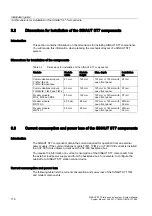
Dimensions for installation of the components
Table 3-2
Dimensions for installation of the SINAUT ST7 components
Module
Module
width
Module
height
Max. depth
Installation
on
Communications module
TIM 3V-IE and
TIM 3V-IE Advanced
40 mm
125 mm
120 mm or 150 mm with
open front panel
S7 rail
Communications module
TIM 4R-IE, TIM 3 and TIM 4
80 mm
125 mm
120 mm or 180 mm with
open front panel
S7 rail
Modem module
MD2, MD3 and MD4
80 mm
125 mm
120 mm or 180 mm with
open front panel
S7 rail
Modem module
MD720-3
22.5 mm
99 mm
120 mm or 140 mm with
open front panel
DIN rail
35 mm
Modem module
MD740-1
45 mm
99 mm
120 mm or 160 mm with
open front panel
DIN rail
35 mm
3.3
Current consumption and power loss of the SINAUT ST7 components
Introduction
The SINAUT ST7 components obtain the current required for operation from an external
power supply. If the communications module TIM 3 / TIM 4 or a TIM 3V-IE variant is installed
in an S7-300, it also draws current over the S7-300 backplane bus.
You require the information on current consumption of the SINAUT ST7 components from
the external load power supply and from the backplane bus, for example, to configure the
cabinet for a SINAUT ST7 station control device.
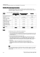
Current consumption and power loss
The following table lists the current consumption and power loss of the SINAUT ST7 TIM
and modem components.


