Installing and putting a TIM into operation
5.1 Design of the TIM 3V-IE variants
SINAUT ST7 Station control system - System Manual
154
System Manual, 05/2007, C79000-G8976-C178-06
5.1.2
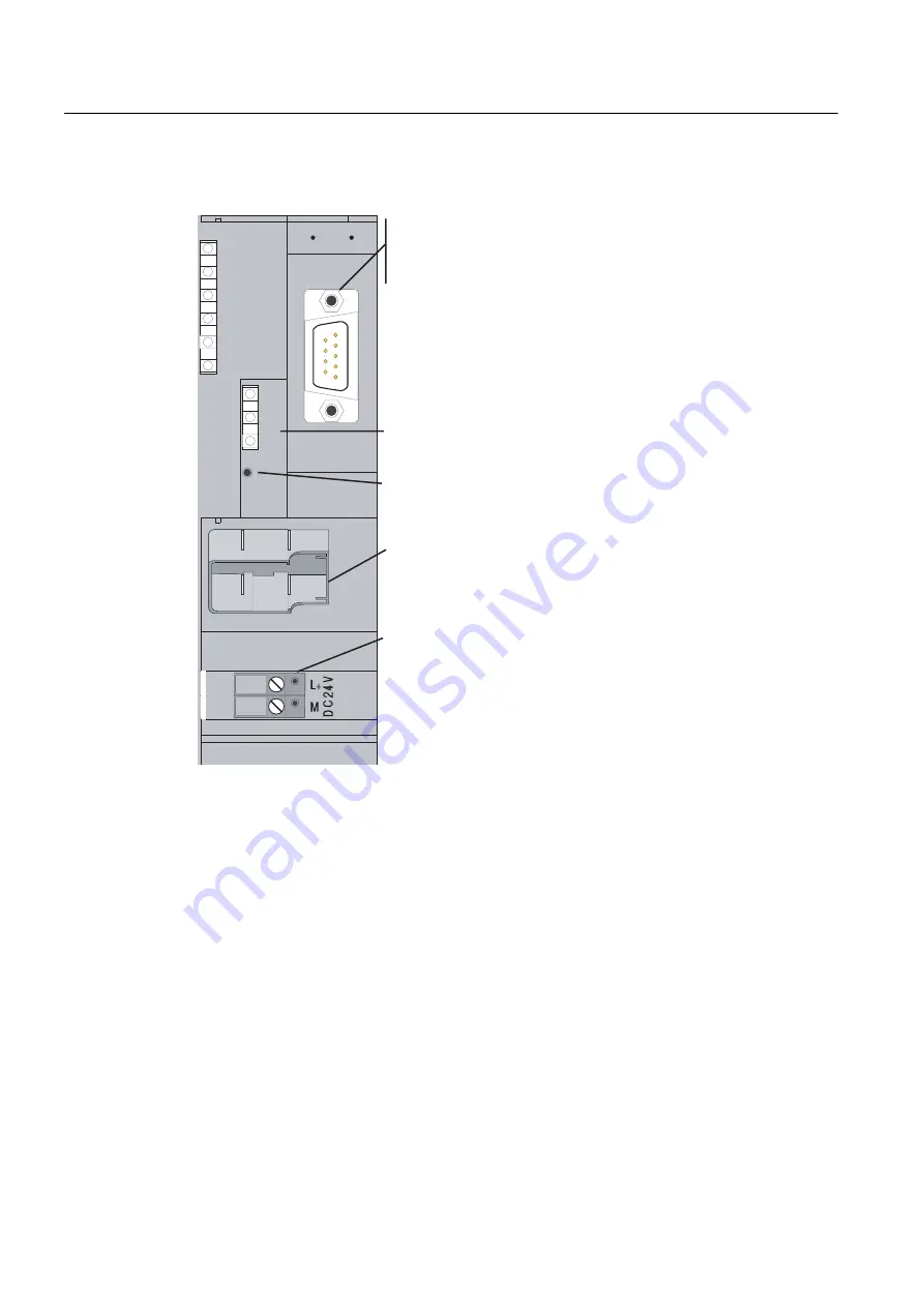
Front view of the TIM 3V-IE variants with front panel removed
5HVHW
9
581
6723
5;7;
6)
/,1.
7['
5['
.%XV
&RQQHFWRUIRU9'&SRZHUVXSSO\
SLQFRQQHFWRU
56SRUWIRUFRQQHFWLQJDQH[WHUQDO
PRGHPRURWKHUWUDQVPLVVLRQHTXLSPHQW
5-MDFN
(WKHUQHW&RQQHFWLRQ
5(6(7EXWWRQ
UHIHUWRQRWHXQGHUILJXUH
)XUWKHUGLVSOD\HOHPHQWV/('V
Figure 5-2
Front view of a TIM 3V-IE variant with front panel removed
For information on the RESET button, refer to "Default startup" in the section "Startup
activities of the TIM 3V-IE variants".
5.1.3
LEDs of the TIM 3V-IE variants
The following table summarizes the meaning of the nine LEDs during normal operation. The
display during startup is explained in the section "Startup activities of the TIM 3V-IE variants
(Page 221)".


