Installing and putting a TIM into operation
5.4 Options for attachment and settings of the TIM 3 and TIM 4 variants
SINAUT ST7 Station control system - System Manual
System Manual, 05/2007, C79000-G8976-C178-06
197
Note
The 6NH7700-3BR60 connecting cable has a ferrite at one of the cable ends to suppress
electromagnetic interference over the connecting cable. You should not normally remove the
ferrite. Make sure that the RJ-12 Western connector at the end of the cable with the ferrite is
connected to the modem.
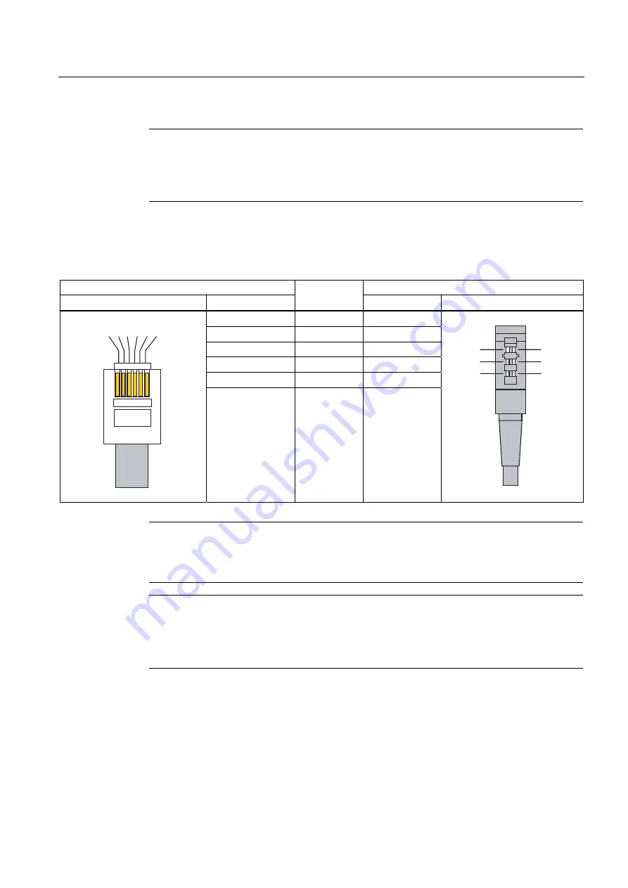
The following table shows the pinout of the RJ-12 Western plug at the modem end of the
standard connecting cable described above and the fitted TAE6N connector.
Table 5-34 Pinout of the RJ-12 and TAE6 connectors
RJ-12 plug
TAE6 plug
Illustration
Pin no.
Signal name
Pin no.
Illustration
4
a1
1
3
b1
2
6
G
3
1
E
4
5
b2
5
2
a2
6
Note
To insert the cable in the X3 RJ-12 jack of the modem, it is best to hold the cable directly
below the RJ-12 plug. This makes it easier to insert the plug than if you hold the RJ-12 plug
itself. When inserting it, make sure that you can hear the RJ-12 connector click into place!
Note
If the MD3 modem is used outside Germany, a country-specific telephone adapter plug can
be fitted to the RJ-12 Western plug. Some countries use the RJ-12 jack in their telephone
outlets which means that the 6NH7700-3BR60 cable can be plugged in directly without an
adapter.
Connecting the TIM 33 to the telephone outlet
The following figure summarizes how the TIM 33 (and all other TIM variants with an
integrated MD3 modem) is connected to the telephone outlet (TAE6N jack) using the
specified standard connecting cable. A telephone can also be connected to the same
telephone outlet as the modem (using the TAE6F jack).


