Installing and putting a SINAUT modem into operation
6.4 MD2 dedicated line modem
SINAUT ST7 Station control system - System Manual
242
System Manual, 05/2007, C79000-G8976-C178-06
You will find examples of connecting the MD2 to a TIM, parallel connection of more than one
MD2 to connect a star ring network to a TIM, or the interconnection of two MD2s to form a
repeater below in the section
Connecting the MD2 to TIM, LTOP and dedicated line
.
6.4.2
Configuration switches accessible from above
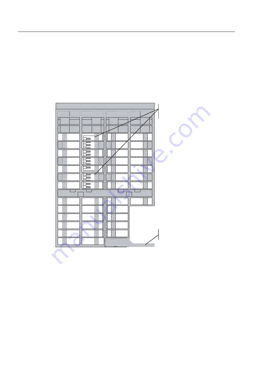
The following figure shows the MD2 modem from above. It indicates the location of the 5-pin
and 10-pin DIL switches that are accessible from above.
SLQSLQ',/VZLWFKIRUVHWWLQJWKH
UHTXLUHGIXQFWLRQRIWKH0'GHGLFDWHG
OLQHPRGHP
)URQWSDQHOODEHOHGಪ0RGHPಫ
Figure 6-10 View of the MD2 modem from above
Settings with the DIL switches accessible from above
The following figure shows the settings possible on the 5-pin and 10-pin DIL switches. These
switches can be accessed from above through the grill in the modem housing.


