background image

Connecting and Switching on the Computing Unit

Release 04/02

3-5

Panel PC 670 Computing Unit, Equipment Manual

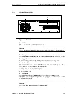
3.2

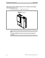
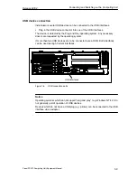
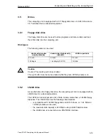
View of Drive Side

1

2

4

3

5

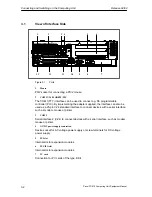
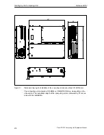
Figure 3-2

Drive side

1

Unit fan

The air vents for the unit fan are located here.

Caution

The air vents must never be covered up, otherwise there is a risk of overheating.

2

Rating plate

The rating plate contains the order no. and production serial no. (F-No.) of the unit.

3

Floppy disk drive

A standard floppy disk drive (1.44 MB) is installed in the computing unit.  

4

Front interfaces

The front interfaces are located behind the cover plate below the floppy disk drive.
They serve for the connection of operating fronts:

S

I/O port for connecting front components

S

LVDS display port

5

Reset button

The reset button can be operated with the aid of a pointed object (e.g. a
straightened paper clip). Pressing the Reset key triggers a hardware reset. The PC
is restarted (cold start).

Caution

There may be a loss of data with a hardware reset.

Summary of Contents for SIMATIC PC 670

Page 1: ...aining and Extending the Computing Unit 4 Configuring the Computing Unit in BIOS Setup 5 Fault Diagnosis 6 Hardware Information 7 Distributed Configuration 8 Appendices A C Glossary Index Release 04 02 Panel PC 670 Computing Unit Equipment Manual SIMATIC PC This manual is only valid for computing units with Order No 6AV77xx ...

Page 2: ...if not avoided may result in minor or moderate injury Caution used without the safety alert symbol indicates a potentially hazardous situation which if not avoided may result in property damage Notice indicates that unwanted events or status can occur if the relevant information is not observed Note draws your attention to particularly important information on the product handling the product or t...

Page 3: ...and software However discrepancies cannot be exclu ded with the result that we cannot guarantee total compliance The informa tion in this publication is however checked regularly and any necessary corrections are included in the following editions We welcome any suggesti ons for improvement Exclusion of Liability Copyright Siemens AG 2002 Allrights reserved The transmission and reproduction of thi...

Page 4: ...For your notes ...

Page 5: ...n options for the computing unit on the configuration error diagnostics and the hardware S SIMATIC Panel PC 670 870 Operating Unit Equipment Manual The equipment manual contains information on operating the operating unit error diagnostics and the hardware S SIMATIC Panel PC 670 870 Installation Guide This Installation Guide contains the information on the mechanical and electrical installation of...

Page 6: ... keys and buttons are shown in a different type face History Release Comments 03 00 Initial release of the SIMATIC Panel PC 670 Computing Unit equipment manual 12 01 Extension to include Remote mount form factor option of the SIMATIC Panel PC 670 Computing Unit equipment manual 04 02 Technical update to the SIMATIC Panel PC 670 Computing Unit equipment manual Trademarks The following designations ...

Page 7: ... 911 895 7001 GMT 01 00 Europe Africa Nuremberg Authorization Local time Mon Fri 8 00 to 17 00 Telephone 49 911 895 7200 Fax 49 911 895 7201 E Mail authorization nbgm siemens de GMT 1 00 America Johnson City Technical Support and Authorization Local time Mon Fri 8 00 to 19 00 Telephone 1 423 461 2522 Fax 1 423 461 2289 E Mail simatic hotline sea siemens com GMT 5 00 Asia Australia Singapore Techni...

Page 8: ...utomation service support Training Center Siemens offers a number of training courses to familiarize you with the SIMATIC S7 automation system Please contact your regional training center or our central training center in D 90327 Nuremberg Germany for details Telephone 49 911 895 3200 Internet http www sitrain com E Mail info sitrain com Other Sources of Assistance In case of technical queries ple...

Page 9: ...hery Units 3 6 3 4 Working with PC Cards 3 10 3 5 Drives 3 13 3 5 1 Floppy disk drive 3 13 3 5 2 LS240 drive 3 13 3 5 3 Hard disk drive 3 16 3 5 4 CD ROM drive or CD RW DVD drive depending on unit equipment 3 16 3 6 Backup Battery 3 17 3 7 Using the Computing Unit in a SIMATIC S5 Network 3 18 3 8 Using the Computing Unit in a SIMATIC S7 Network MPI DP 3 22 3 9 Networking the Computing Unit and Oth...

Page 10: ...ssor Upgrade 4 26 4 11 Reset button 4 27 5 Configuring the Computing Unit in BIOS Setup 5 1 5 1 Modifying the Device Configuration with SETUP 5 2 5 1 1 Menu Main 5 5 5 1 2 Menü Advanced 5 15 5 1 3 Menü Security 5 22 5 1 4 Menu Power 5 24 5 1 5 Menu Boot Sequence 5 25 5 1 6 Menu Version 5 27 5 1 7 Menu Exit 5 28 5 1 8 Setup default settings 5 29 5 2 Configure PC Card interface 5 32 6 Fault Diagnosi...

Page 11: ...7 32 7 6 1 Design and Theory of Operation 7 32 7 6 2 Pin assignmentI SA slot 7 32 7 6 3 Pin assignment PCI slot 7 34 7 7 Power supply AC and DC 7 37 7 8 Connecting cables 7 38 8 Distributed configuration 8 1 8 1 Description 8 2 8 1 1 Overview 8 2 8 1 2 Dimensions 8 3 8 1 3 Mounting 8 3 8 2 Cable connection 8 4 8 3 Spare parts 8 4 8 4 Technical data 8 4 A Technical Data A 1 A 1 Technical Data of th...

Page 12: ...Contents Release 04 02 xii Panel PC 670 Computing Unit Equipment Manual ...

Page 13: ...nt Manual Product Overview Chapter Overview In Section You Will Find on Page 1 1 Advantages of the computing unit 1 2 1 2 Safety notes 1 4 1 3 Certificates guidelines and declarations 1 8 1 4 Certification for USA Canada and Australia 1 10 1 ...

Page 14: ...ibutable for example by S extensive climate vibration and shock tests to ensure industrial compatibility S hotline service spare parts S compact dimensions S suitability for use in a wide ambient temperature range S a design that is easy to service and maintain Installation The computing unit can be installed in virtually all the usual locations refer to Chapter 2 2 There are anchorage points on b...

Page 15: ...ly suitable for use on site under harsh industrial conditions It meets the specific requirements of an industrial environment such as noise immunity compliance with standards ruggedness and continuous operation S Owing to the variable operating location and the many options for installation the computing unit can be used virtually anywhere S Integrated on the computing unit are all the ports requi...

Page 16: ... a cold environment condensation may occur Before starting up the device must be dry and therefore an acclimatization period of at least 12 hours is necessary Before installing and operating the device please note the information on ambient conditions in the Appendix Technical Data and and on installing the device in Chapter 2 2 The device must be installed in such a way that it presents no danger...

Page 17: ...the safety guidelines of the country concerned Check to make sure that the rated voltage for the device corresponds to that supplied by the local power supply This device is equipped with a safety tested power supply cable and may be connected only to a socket outlet with grounding contact Make sure that the socket outlet on the device or the socket outlet with grounding contact of the building wi...

Page 18: ... be used conductor cross section at least 18 to AWG and grounding type plug 15 A 250 V Make sure that the cable set complies with the safety standards of the country where the devices will be installed and that they bear the relevant markings Repairs Repairs to the Panel PC may only be carried out by authorized adequately trained personnel Warning Unauthorized opening and repairs to devices can le...

Page 19: ...atteries observe the locally applicable laws on disposal of pollutants ESD guidelines Components containing ESD Electrostatically Sensitive Devices may be identified by the following label When handling components containing ESD it is essential to observe the following guidelines S Before working with components containing ESD you must discharge any static electricity from your body e g by touchin...

Page 20: ...an AC power supply comply with the standards EN 61000 3 2 1995 harmonic currents and EN 61000 3 3 1995 voltage fluctuations and flicker Caution This is Class A equipment The equipment may cause radio interference in residential areas in such cases the operator can be requested to take reasonable countermeasures Low voltage guidelines The devices with AC power supply meet the requirements of EU Gui...

Page 21: ...hery equipment suitable for industrial demands is connected in accordance with EN50082 2 1995 Periphery devices should only be connected using shielded cables DIN ISO 9001 certificate The quality assurance system of our entire product production process development production and sales meets the requirements of DIN ISO 9001 corresponds to EN29001 1987 This was confirmed by the DQS Deutsche Gesells...

Page 22: ... Canadian Standard C22 2 No 950 I T E or complying with C22 2 No 142 IND CONT EQ Underwriters Laboratories UL complying with Standard UL 1950 Report E11 5352 and Canadian Standard C22 2 No 950 I T E or complying with UL508 and C22 2 No 142 IND CONT EQ or complying with UL508 and C22 2 No 142 IND CONT EQ UL Recognition Mark Canadian Standard Association CSA complying with Standard C22 2 No 950 LR 8...

Page 23: ...ference at his own expense Shielded Cables Shielded cables must be used with this equipment to maintain compliance with FCC regu lations Modifications Changes or modifications not expressly approved by the manufacturer could void the user s authority to operate the equipment Conditions of Operations This device complies with Part 15 of the FCC Rules Operation is subject to the following two condit...

Page 24: ...Product Overview Release 04 02 1 12 Panel PC 670 Computing Unit Equipment Manual Australia This product meets the requirements of the AS NZS 3548 Norm ...

Page 25: ...ment Manual Starting Up the Computing Unit Chapter Overview In Section You Will Find on Page 2 1 Unpacking and checking the computing unit 2 2 2 2 Installing the computing unit 2 3 2 3 Ensuring Readiness for Service 2 7 2 4 Transport 2 9 2 ...

Page 26: ... the package contents for any visible damage Entering the production number SVP number 5 Record the serial number SDVP number of your computing unit in the table you will find it on the rating plate above the floppy disk drive on the side of the device The SVP number and MLFB number provide unique identification of the device or repairs or in the case of theft Entering the Microsoft Windows Produc...

Page 27: ...ly design must fulfill the fire protection housing requirements Please observe the following points when installing your device S Avoid extreme ambient conditions as far as possible Protect the device from dust moisture and heat S Do not expose your device to direct sunlight S The device must be installed in such a way that it presents no danger of any kind for example by tipping over S The cleara...

Page 28: ...297 80 267 11 Figure 2 1 Dimension drawings for installation of the computing unit device without CD ROM drive The computing unit contains a CD ROM or CD RW DVD drive depending on the unit version The installation depth of the computing unit is increased by 21 mm as a result of its installation ...

Page 29: ...sitions for the computing unit complying with UL1950 EN60950 CSA22 2 No 950 An angle of inclination of 20_ is allowed installation position Position 1 preferred position Position 2 Position 3 desktop Position 4 cover Not permitted where an LS240 drive is installed Not permitted where a disk CD ROM LS240 drive is installed ...

Page 30: ...sition for the computing unit complying with UL508 CSA 22 2 No 142 An installation angle of 15_ is permitted in this position Position 5 interfaces at bottom Note The possible installation locations for the computing unit do not agree with the permissible installation location of Panel PC 670 refer to the commissioning instructions ...

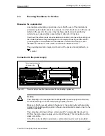
Page 31: ...is to be installed The minimum cross section should not be less than 5 mm2 The grounding terminal is located on the side of the device and is identified by a symbol Connection to the power supply Power supply connection Unit power plug Figure 2 2 Power supply connection device socket for non heating appliances Caution The computing unit is equipped with a safety tested power supply cable and may b...

Page 32: ...ect the front panels ready for operation 1 Plug the connection cables into the corresponding sockets on the interface side of the computing unit refer to Panel PC 670 870 Computing Unit equipment manual 2 Once the peripheral devices have been connected the device is ready for mains operation Connect your device to the mains supply The computing unit is now operating Switching the computing unit of...

Page 33: ... transport Only the original packing should be used when dispatching the Panel PC Caution Risk of damage to the computing unit When in transit in cold weather and the computer is subjected to extreme differences in temperature care must be taken to ensure that moisture is not deposited on or in the device moisture condensation Allow the computer to warm up slowly to room temperature before putting...

Page 34: ...Starting Up the Computing Unit Release 04 02 2 10 Panel PC 670 Computing Unit Equipment Manual ...
Page 35: ...necting Peripheral Devices 3 6 3 4 Working with PC Cards 3 10 3 5 Drives 3 13 3 6 Backup battery 3 17 3 7 Using the Computing Unit in a SIMATIC S5 Network 3 18 3 8 Using the Computing Unit in a SIMATIC S7 Network MPI DP 3 22 3 9 Networking the Computing Unit and Other Nodes via PROFIBUS 3 24 3 10 Networking the Computing Unit and Other Computers via Industrial Ethernet 3 25 3 11 Connection under W...

Page 36: ...nting the adapter supplied the interface can also be used as a 25 pin V 24 standard interface to connect devices with a serial interface such as modem mouse or printer 3 COM 2 Serial interface 2 V 24 to connect devices with a serial interface such as modem mouse or printer 4 AC DC power supply connection Device socket for AC voltage power supply or screw terminals for DC voltage power supply 5 PCI...

Page 37: ...printers modems or mouse and keyboard Older operating systems do not support this interface 11 VGA A VGA monitor can be connected here 12 LPT1 The parallel interface serves to connect devices with a parallel interface e g a printer 13 Keyboard Connection for a PS 2 keyboard Caution When connecting periphery units always be sure to use shielded cables and metal connectors to avoid invalidating your...

Page 38: ...ation of a flat display and an external monitor If no front display element is connected the external monitor is used for the display at a resolution of 640 x 480 pixels Modes with a lower resolution and text modes are expanded to this format To optimize the display on the external monitor set CRT LCD selection CRT enabled in Setup in the Main menu using the Hardware Options dialog box A resolutio...

Page 39: ...serial no F No of the unit 3 Floppy disk drive A standard floppy disk drive 1 44 MB is installed in the computing unit 4 Front interfaces The front interfaces are located behind the cover plate below the floppy disk drive They serve for the connection of operating fronts S I O port for connecting front components S LVDS display port 5 Reset button The reset button can be operated with the aid of a...

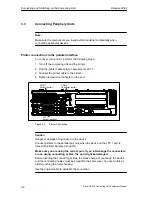
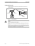
Page 40: ...ter 4 Tighten screw the connector on the port COM 1 Socket serial COM 2 Connector serial LPT1 Socket parallel Figure 3 3 Printer Connection Caution Danger of damage being caused to the device Connect printers to the parallel port only when the device on the LPT 1 port is turned off printer likewise turned off Make sure you are using the correct port If you interchange the connectors or use wrong c...

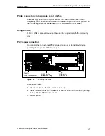
Page 41: ... manual for your printer Using a mouse A PS 2 USB or a serial mouse can be used in conjunction with the computing unit PS 2 mouse connection You can connect an external PS 2 mouse or another external input device pointing device to the PS 2 mouse port PS 2 mouse socket Port for COM 2 Port for Serial mouse plug USB port for USB mouse Figure 3 4 Connecting the Mouse Proceed as follows 1 Disconnect t...

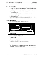
Page 42: ...ice off 2 Plug your serial mouse onto the mouse connector labeled COM 2 3 Screw the connector tight 4 Restart your device How to connect a USB mouse is described in Connecting USB devices below PS 2 Keyboard connection You can connect a PS 2 keyboard to the computing unit Port for PS 2 keyboard Figure 3 5 Connecting a PS 2 Keyboard Proceed as follows 1 Disconnect the computing unit from the mains ...

Page 43: ...ted by the Plug and Play operating system Any necessary drivers are requested by the operating system If more than two USB devices are to be connected use a HUB Both interfaces can be used as High Current interfaces USB interfaces Figure 3 6 USB connection ports Notice Operating systems which do not support plug and play e g Windows NT 4 0 do not generally permit operation of USB devices Devices w...

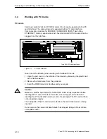
Page 44: ...ote of the following when working with Cardbus PC cards 1 Open the port cover on the left side of the device by loosening the plastic rivet with a flat screwdriver 2 Remove the metal cover from the guide rail 3 Insert the PCMCIA card or Cardbus card you require Caution Make sure that the eject button for Cardbus PC cards is fully depressed before inserting the PC card If this is not the case a car...

Page 45: ...bus PC cards by briefly touching a grounded object refer also the ESD Guideline Appendix B Damage could occur if you do not Note Peak currents of 650 mA at 5 V referred to 3 s are allowed Examples of PCMCIA cards on the PC card interface for hard disk drive 330 mA read write Maxtor MXL 131 III 640 mA spin up 2 s 110 mA idle fax modem 60 mA idle Dr Neuhaus 140 mA transfer Ethernet XIRCOM 150 mA ...

Page 46: ...urce Exclusion to reserved default available Caution Danger of PC cards and the computing unit being damaged The PC card must be plugged into the interface with its front facing the rear side of the computing unit This side is normally marked with a company or product name and the wording This side up or something similar If the PC card is inserted incorrectly the computing unit and PC card may be...

Page 47: ... LS240 superdisks 3 5 inch 3 5 inch 3 5 inch 720 Kbyte 1 44 Mbyte 135 TPI 120 MB Caution Caution This could result in loss of data The eject button must never be pressed while the green LED drive lamp is on 3 5 2 LS240 drive As an alternative to a floppy disk drive the computing unit can be equipped with an LS240 drive for customized solutions The LS240 can save larger amounts of data on data medi...

Page 48: ...ton Eject button Access light Drill hole for emergency ejection LS240 only Figure 3 8 Handling Floppy Disks Caution Caution This could result in loss of data The eject button must never be pressed while the LS240 s green LED drive lamp is on LS240 drives are very sensitive when it comes to unacceptable vibrations During operation vibrations might damage the drive and or the data medium Refer to th...

Page 49: ...ndard disks Notice Observe the following to ensure reliable operation and high degrees of data integrity S Keep and transport superdisks in the protective cassette provided This protects the data medium from dust and dirt S Only remove the superdisk from the drive when no reading or writing operations are in progress The data medium is protected from particles of dirt Do not expose the data medium...

Page 50: ...ion depth of the computing unit is increased by 21 mm as a result of its installation Operation After pressing the Open Close button the CD DVD tray is extended following a short delay Insert the CD DVD in the tray with the inscription side up The CD DVD tray is automatically retracted after either pushing the tray lightly or pressing the Open Close button Press the Eject button to extend the CD t...

Page 51: ...uately trained personnel Observe the information in the documentation on the CPU module When disposing of the batteries observe the locally applicable laws on disposal of pollutants Caution Improper replacement of the battery poses a danger of explosion Only replace with batteries of the same type or those of a similar type recommended by the manufacturer Dispose of used batteries according to the...

Page 52: ...cables are less susceptible to inductive interference A low line resistance result in reduced voltage excursions and shorter charge reversal times the line resistance decreases with increasing conductor cross section for the same length of cable S The shorter the data transmission link the higher the maximum possible transfer rate S If there is an active transmitter and an active receiver at the s...

Page 53: ...g the connecting cable into the corresponding port on the CPU of the programmable controller 5 In order to enable TTY operation you must set TTY to enabled in the BIOS setup Access the BIOS Setup by pressing the F2 key during the boot routine Caution Danger of damage being caused to the device If you interchange the connectors or use wrong connecting cables the port might be damaged Be careful not...

Page 54: ...ection Connecting cable Order No Adapter 6ES5 734 2BF00 COM 1 as Computing unit to a SIMATIC S5 6ES5 731 1xxx0 15 pin 6ES5 731 6AG00 TTY port programmable controller 6ES5 731 0xxx0 25 pin 6ES5 731 6AG00 In order to maintain a data transmission rate of 9600 bps up to a distance of 1000 m the receive diode is connected to ground reference via the connecting cable Note Lengths deviating from the stan...

Page 55: ...d 6ES5 731 6AG001 6ES5 731 6AG00 Notice 1 When connected in series it is essential to connect the cable in the right direction refer to Figure 3 10 2 The connecting cable is available for order only as a spare part A description of the connecting cables is provided in Chapter 7 Adapter Connecting cable Active Passive 6ES5 731 6AG00 6ES5 733 2xxx0 PG 7xx PG 6XX Figure 3 10 Direction of Connection A...

Page 56: ... Interface 6ES7901 0BF00 0AA0 5 m long In interference environment Bus connector 6ES7972 0BB10 0XA0 or 6ES7972 0BB20 0XA0 Figure 3 11 Connection Using the MPI DP Interface To connect the computing unit to a SIMATIC S7 programmable controller perform the following steps 1 Disconnect the computing unit from the mains power supply 2 Plug the connecting cable onto the MPI DP interface Caution Danger o...

Page 57: ... interface to form a network segment The physical connection to the MPI PROFIBUS DP network is via an isolated RS485 interface which is an integral part of the PC s basic board Several MPI PROFIBUS DP network segments can be connected via repeaters The complete MPI PROFIBUS DP network can consist of up to 127 nodes Data transmission rates of 9 6 Kbits to 12 Mbit s are possible using the PROFIBUS D...

Page 58: ... the network functions The network operates on the token passing with subordinate master slave principle complying with DIN 19245 PROFIBUS It distinguishes between active and passive nodes An active node receives the token and passes it on to the next node within a specified time Hardware requirements Using the following components for example you can connect or network the computing unit to with ...

Page 59: ...PCI adapter The interface is Plug Play capable and is automatically detected in Windows The protocol settings are defined in the Windows Control Panel Notice In order to operate the 100 Mbaud an Class 5 Ethernet cable is required Note Please refer to the SIMATIC NET Catalog IK IP for more information on the SIMATIC Net PC cards 3 11 Connection Using Windows Windows supports point to point connecti...

Page 60: ...Connecting and Switching on the Computing Unit Release 04 02 3 26 Panel PC 670 Computing Unit Equipment Manual ...
Page 61: ...he safety notes it contains In Section You Will Find on Page 4 1 Opening the Device 4 2 4 2 Installing Additional Memory 4 8 4 3 Replacing the Backup Battery 4 10 4 4 Installing Expansion Boards 4 12 4 5 Removing and Installing Drives 4 17 4 6 Removing and Installing the Power Supply 4 22 4 7 Removing and Installing the Bus Board 4 23 4 8 Removing and Installing the Motherboard 4 24 4 9 Removing a...

Page 62: ...measures are therefore necessary when handling such components These measures are explained in the guidelines for electrostatic sensitive devices at the end of this manual ESD Guidelines Restricted liability All technical specifications and approvals apply only to expansion modules approved by Siemens AG No liability can be accepted for impairment of functions caused by the use of non Siemens devi...

Page 63: ...scharge the electrostatic charge from tools you are using S Wear a grounding strap when handling components S Leave components and component parts in their packaging until you are ready to install them S Disconnect the device from its power supply before plugging in or removing any components or component parts S Touch components and module only on their edges Do not touch contact pins or printed ...

Page 64: ...nector and remove all interconnecting cables and connecting cables from the device including the keyboard cable 2 Remove the computing unit from its mounting cabinet only necessary if mounting screws are inaccessible as a result of installation 3 Undo the two screws refer to Figure 4 1 on the housing cover 4 Raise the cover slightly 5 You can then remove the housing cover Screws on the housing cov...

Page 65: ... Manual 4 1 3 Functional Units Visible After Opening the Device View The function units become visible after removing the top cover of the unit and removing the hard disk module Power supply unit Processor Wiring backplane Memory expansion module Disk drive or LS 240 Fan Figure 4 2 Computing unit open ...

Page 66: ...1 4 Motherboard The motherboard is the heart of the computing unit Here data are processed and stored and interfaces and device I Os are controlled X44 X400 X402 X401 S1 X1 X20 X19 X700 X29 X28 X128 X71 X70 X10 X500 X600 X40 X11 X9 X6 X13 X26 X31 X5 X4 X3 X25 X420 X24 X14 X23 T1 T2 T3 X41 Figure 4 3 Motherboard ...

Page 67: ...onnection for 105 W power supply X14 Connection for 85 W power supply X19 X20 System memory 2 slots X23 Not connected X24 Connector for clock battery X26 Connector alternative COM2 X28 Not connected X29 Plug for CPU fan X31 IDE connector for LS 120 X40 USB bus connector X41 IDE connector for 3 5 hard disk X44 Plug for front interfaces X70 X71 TTY sender receiver X128 Connector for unit fan X400 Co...

Page 68: ...memory The motherboard has 2 slots for 144 pin SO DIMM memory modules This allows you to expand the memory capacity of your computing unit to 512 Mbytes One or two modules can be equipped Memory Modules 64 MB 128 MB 256 MB 64 MB 1 128 MB 2 128 MB 1 192 MB 1 1 256 MB 1 256 MB 2 384 MB 1 1 512 MB 2 Bank 0 Bank 1 Figure 4 4 Position of SO DIMM memory modules ...

Page 69: ...ling the SO DIMM Modules To insert the modules perform the following steps 1 Open the unit first as described in section 4 1 2 Insert the modules into the sockets Note the cutout locking element on the connector side of the SO DIMM module 3 Press the module down applying light pressure until it locks into place 4 Close the device Caution Danger of damage The modules must be fitted firmly in the sl...

Page 70: ...years The battery seldom needs to be replaced for that reason Battery voltage too low If the battery voltage is too low the time is lost and a correct configuration of the device can no longer be guaranteed Replacing the battery In this case you must replace the backup battery The battery is located on the motherboard To change the battery perform the following steps 1 Disconnect the unit from the...

Page 71: ... replace the lithium battery with an identical battery or with a type recommended by the manufacturer Order No W79084 E1003 B1 If possible return old lithium batteries to the manufacturer or recycling facility or dispose of them as special waste Changing SETUP If you change a battery or unplug the battery connector you must run SETUP to reset your device s configuration data refer to Chapter 5 ...

Page 72: ... PCI specification The dimensions of the cards must not exceed the stated dimensions If the height is exceeded contact problems malfunctions and difficulties with installation cannot be ruled out The illustrations show full length AT PCI cards Depending on the slot there might be constraints concerning the overall length 175 mm 106 7 mm A31 A1 6 89 4 201 Figure 4 6 XT card 121 92 mm A31 A1 C18 C1 ...

Page 73: ...re 4 8 Short PCI card 5 V 265 mm 10 48 106 68 mm 4 2 8 19 mm 0 322 Figure 4 9 Long PCI card 5 V Note on long PCI cards Before long PCI cards can be inserted in the guides of the fan trough they must be fitted with an extender this should be included with the long PCI board Long PCI cards can be inserted in the guides of ISA modules by means of this extender ...

Page 74: ...hich the slide elements are inserted To change the battery perform the following steps 1 Open the housing as described in section 4 1 2 Undo the fixing screw of the module retainer plate 3 During assembly ensure that the module retainer plate is resting on the guide on the system housing Guide slits for slide elements Fixing screw of module retainer plate Figure 4 10 Removing and installing an exp...

Page 75: ...t the slide element through the guide slit until it is resting firmly on the module The module must now be introduced into the notch Caution Do not exert pressure on the module Therefore do not use force to press the slide module onto the module 2 Remove the surplus slide element Score the slide element at the top edge of the support with a knife and snap it off Nip off the surplus with a sharp si...

Page 76: ... described in section 4 1 2 Disconnect all the connectors from the expansion module and note their assignment 3 Remove the module retainer plates as described in section 4 4 1 4 Undo the screw on the slot plate of the module 5 Pull the module out of its slot 6 Proceed in the reverse order to install the new expansion module Slots for expansion boards Module retainer plate Figure 4 11 Removing and ...

Page 77: ...emove the 4 screws on the back of the system housing 2 Swing open the drive cage 3 Detach the drive holder from its mounting and place it face down on the housing 4 Make a note of the cable assignment and detach the cables 5 Loosen the 4 screws with which the hard disk drive is secured to the shock absorbing part of the holder Remove the hard disk drive from the holder 6 Proceed in the reverse ord...

Page 78: ...Maintaining and Extending the Computing Unit Release 04 02 4 18 Panel PC 670 Computing Unit Equipment Manual Figure 4 13 Hard disk drive with holder removed ...

Page 79: ...depth of the computing unit is increased by 21 mm as a result of its installation 1 Undo the 2 screws on the back of the system housing 2 Remove the cover of the CD ROM drive 3 Undo the three screws which secure the CD ROM on the mounting 4 Remove the CD ROM drive from the mounting and carefully pull off the data cable 5 Proceed in the reverse order to install the new drive CD ROM drive with cover...

Page 80: ...n 4 5 1 3 Undo the interlocking of the controller flexible cable on the motherboard and pull the flexible cable out of the plug connection 4 Undo the two fixing screws TORX T8 on the housing 5 Lift the floppy disk drive up and out of the housing 6 Proceed in the reverse order to install the new drive The new drive must be of the same type as the one removed Floppy disk drive fixing screws Figure 4...

Page 81: ... as described in Chapter 4 1 2 Remove the drive mounting as described in section 4 5 1 3 Release the cable clamp assembly of the controller flexible cable on and pull the flexible cable out of the plug connection 4 Undo the two fixing screws TORX T8 on the housing 5 Lift the LS240 drive up and out of the housing 6 Proceed in the reverse order to install the new drive LS240 drive fixing screws Scre...

Page 82: ...Remove the 3 screws from the cover of the power supply unit from the housing 4 Disconnect the internal SV cable on the power supply only applicable to units with 105 W power supplies 5 Remove the two fixing screws TORX T10 on the housing 6 Pull the power supply unit up and out of the housing 7 Proceed in the reverse order to install the new power supply unit Cover of the power supply unit Power su...

Page 83: ...om their slots perform the steps described in section 4 4 2 3 Remove the drive mounting as described in section 4 5 1 4 Remove the power supply unit as described in section 4 6 5 Undo the screw on the motherboard 6 Pull the wiring backplane from the motherboard 7 Proceed in the reverse order to install the new wiring backplane Wiring backplane Wiring backplane fixing screws Figure 4 18 Removing an...

Page 84: ... Remove the drive mounting as described in section 4 5 1 4 Remove the power supply unit as described in section 4 6 5 Undo 7 screws on the motherboard and undo 10 hexagon head cap screws at the interfaces 6 Remove the wiring backplane and the motherboard 7 Proceed in the reverse order to install the motherboard Fixing screws on the motherboard Figure 4 19 Fixing screws on the motherboard The mothe...

Page 85: ...from the motherboard 3 The fan is secured to the housing by two plastic rivets Undo the rivets by pressing out the gudgeon from the rear of the rivet shank 4 Remove the fan 5 Proceed in the reverse order for assembly Unit fan Plastic rivets Figure 4 20 Removing and installing the fan Notice Fit only a fan of the same type Caution To ensure that the device is adequately cooled ensure that the runni...

Page 86: ...slot 3 5 Insert the new processor in the slot ensuring that the marking on the top side of the processor coincides with the position of the marking 4 on Slot A Caution The marking on the top side of the processor may be covered by the heat sink In such cases align the processor with the marking in the row of pins at the bottom of the processor 6 Pivot the lever back down until it locks into place ...

Page 87: ... device The computing unit is restarted On the computing unit the Reset button is located on the drive side beside the floppy disk drive The Reset button can only be operated with the aid of a pointed object e g the tip of a ball point pen or straightened paper clip The position of the Reset button is marked in the illustration of the computing unit below Reset Button Figure 4 22 Reset button ...

Page 88: ...Maintaining and Extending the Computing Unit Release 04 02 4 28 Panel PC 670 Computing Unit Equipment Manual ...
Page 89: ...g or exchanging an extension board memory expansion module or by replacing a system module In Section You Will Find on Page 5 1 Modifying the Device Configuration with SETUP 5 2 5 1 1 The Main Menu 5 5 5 1 2 The Advanced Menu 5 15 5 1 3 The Security Menu 5 22 5 1 4 The Power Menu 5 24 5 1 5 The Boot Sequence Menu 5 25 5 1 6 The Version Menu 5 27 5 1 7 The Exit Menu 5 28 5 1 8 Default Setup Setting...

Page 90: ...he hardware configuration for example hard disk type and define the system characteristics You can also use SETUP to set the time of day and date Incorrect BIOS Data If there are detected incorrect BIOS data during the boot process you are asked by the BIOS to S Start BIOS SETUP by pressing F2 or S continue booting by pressing F1 start SETUP On completion of the startup test the BIOS gives you the...

Page 91: ... Passed System BIOS shadowed Video BIOS shadowed UMB upper limit segment address Fixed Disk 0 xxxx ATAPI CD ROM Txxx Mouse initialized Press to enter SETUP By pressing the F2 key when the above figure is displayed you will change to the BIOS Setup program based on the ROM In this program you can set a number of system functions and hardware configurations of your programming device The default set...

Page 92: ...ain Menu Example The screen is divided into four sections In the top section you can select the menu screens Main Advanced Security Power Boot Sequence Version Exit In the left of center section you can choose the different settings or submenus Brief help texts appear on the right for the currently selected menu entry The bottom section contains information for operator inputs Yellow stars to the ...

Page 93: ... Hour Minute Second Month Day Year Enter Help F1 Advanced Security Power Boot Sequence Version Exit Main 15 35 32 Help window Figure 5 2 SETUP Main Menu Example Setting in the Main Menu In the Main menu you can move upwards and downwards using the cursor keys and to select the following system parameters Field Meaning System Time For viewing and setting the current time System Date For viewing and...

Page 94: ...ond and the date Month Day Year You can move between the entries in the date and time options for example from hour to minute using the tabulator key Floppy disk A Floppy disk drive Here you can set up the floppy disk drive of your specific computing unit The following entries are possible Disabled if there is no floppy disk drive and there is a LS 240 drive Default setting for an installed LS 240...

Page 95: ...trol Enabled 32 Bit I O Enabled Transfer Mode FPIO 4 DMA 2 Ultra DMA Mode Disabled LBA Format Total Sectors 40031712 Figure 5 3 Primary Master Field Type The parameters you can select here are normally stored on your IDE drive The Auto setting in the Type field means that these values are automatically read from the drive and written into memory Autodetect If Type is selected for a drive that cann...

Page 96: ...ol field If the LBA Mode Control field enabled disabled is set to Enabled the system supports hard disks with capacities greater than 528 Mbytes The value depends on the drive and should be set only by setting the Type field to Auto 32 Bit IO field The box 32 Bit IO defines the access type for the drive Disabled 16 Bit access Enabled 32 Bit access default Transfer Mode and Ultra DMA Mode fields Th...

Page 97: ... 640 KB 121856 MB Enter Help F1 Main 15 35 32 Write Back Disabled Write Through Write Back Controls caching of system conventional memory and memory above one megabyte Figure 5 4 Memory Cache Field A cache is a fast memory buffer between the CPU and main memory DRAM Recurrent memory access operations are executed in the fast cache instead of the main memory if the function is enabled In rare insta...

Page 98: ...llows the system to skip certain tests while booting This will decrease the time needed to boot the system Enter Help F1 Main Boot Options Enabled Summary screen Disabled Enabled Figure 5 5 Boot Options Submenu Quick Boot Mode Some hardware tests are skipped when the system starts up thus speeding up the boot procedure SETUP prompt The message PRESS F2 to enter Setup appears at the bottom of the s...

Page 99: ...eans that the feature is active Disabled means that the feature is inactive Example of a summary screen PhoenixBIOS Setup Utility SIMATIC Box CPU Type CPU Speed System Memory Extended Memory Shadow Ram Cache Ram Hard Disk 0 Hard Disk 1 Hard Disk 3 Hard Disk 2 PC 620 Pentium R III 866 MHz 640 KB 119 MB 384 KB 512 KB 20496 MB None None BIOS Number System ROM BIOS Date COM Ports LPT Ports Display Typ...

Page 100: ...NumLock ESC Exit Selects Power On state for NumLock on next boot Select Item Select Menu Select Change Values Sub Menu F9 F10 Setup Defaults Save and Exit Key Click Disabled Keyboard auto repeat rate Enter Help F1 Main On Keyboard Features Keyboard auto repeat delay 30 sec 1 2 sec Figure 5 7 Keyboard Features Submenu Numlock Switches Numlock on or off following power on Key Click A keystroke can b...

Page 101: ... Slot Enabled SafeCard functions Enabled CRT LCD selection SIMULTAN LCD Screensize Expand DSTN Contrast 154 Fan Control Enabled LAN Remote Boot Disabled Figure 5 8 Hardware Options Submenu The parameters of the interfaces present on the basic module are set here Entry Meaning PCI MPI DP Enables the CP5611 compatible MPI DP interface The recourses are managed by the BIOS PCI plug and play mechanism...

Page 102: ...an be used CRT LCD selection LCD Enabled All data is output only to the internal LCD the 15 way VGA port is disabled CRT Enabled for the highest resolution the display signals are only sent to the 15 pin VGA interface The LCD interface of the VGA controller is disconnected SIMULTAN Both display interfaces are enabled and operate simultaneously Note however that the LCD does not support all resolut...

Page 103: ...n Setup Warning Setting items on this menu to incorrect values may cause your system to malfunction Figure 5 9 Advanced Menu Settings of the Advanced menu Installed O S Plug and Play means that all modules are automatically detected and installed providing they support the Plug and Play functionality other BIOS handles the entire Plug and Play capability default configuration Win98 The operating s...

Page 104: ...u Select Change Values Sub Menu F9 F10 Setup Defaults Save and Exit Enter Help F1 Advanced COM LPT Configuration Configure serial port A using options Disabled No configuration Enabled User configuration Auto BIOS or OS chooses configuration OS Controlled Displayed when controlled by OS Base I O address Interrupt IRQ 4 Internal COM 1 Base I O address Enabled Interrupt IRQ 3 Internal COM2 Mode Enab...

Page 105: ...onal SPP S Standard setting for the 8 bit parallel transfer according to IEEE1284 specifications S Feedback of the output device is only possible via the control cables Bidirectional Standard parallel port bidirectional as for SPP unidirectional however S Feedback of the output device is also possible via the 8 bit data cables EPP Enhanced parallel port S Enhanced parallel port data transfer rate ...

Page 106: ...ce Slot 2 PCI PNP ISA IRQ Resource Exclusion PCI IRQ line 1 PCI IRQ line 2 PCI IRQ line 3 PCI IRQ line 4 Auto Select Auto Select Auto Select Auto Select Figure 5 11 PCI Configuration Submenu PCI Devices Submenu If the PCI devices field is selected the following submenu appears PhoenixBIOS Setup Utility Item Specific Help ESC Exit Select Item Select Menu Select Change Values Sub Menu F9 F10 Setup D...

Page 107: ...to the selected 00E0H values Submenu PCI PNP ISA IRQ Resource Exclusion Available means that the BIOS Plug and Plug device can assign IRQs to Plug and Play compatible modules or main board functions You should only change it Reserved if the specific interrupt is to be assigned to not Plug and Play compatible PCMCIA modules PhoenixBIOS Setup Utility Item Specific Help IRQ 3 ESC Exit Select Item Sel...

Page 108: ...y ISA devices PCI PNP ISA IRQ Resource Exclusion PCI IRQ line 1 PCI IRQ line 2 PCI IRQ line 3 PCI IRQ line 4 Disabled Autoselect 3 4 5 7 9 10 11 12 14 15 PCI Device Slot 1 PCI Device Slot 2 Figure 5 14 PCI Configuration Submenu Disabled No interrupt possible for this PCI IRQ line AutoSelect Plug and Play mechanism in BIOS selects unassigned interrupts and allocates them to the on board PCI devices...

Page 109: ... red with Main Memory Default Primary Video Adapter Frame Buffer Size AGP Rate 8 MB 2x AGP Figure 5 15 Submenu Video Adapter Settings Frame Buffer Size 8 Specifies the size of the graphic memory used 16 Onboard graphic card This range is in the 32 Main memory of the system AGP Rate 1x Specifies the AGP transfer speed to the Onboard 2x graphic card 4x Default Primary Video Adapter AGP The Onboard v...

Page 110: ... Main Enter Fixed disk boot sector Normal Diskette access Supervisor Advanced Security Supervisor Password is Disabled User Password is Disabled Figure 5 16 Security Menu Supervisor Password is Disabled Password not set All setup entries can be processed without a password Enabled Passwort is enabled The BIOS setup can only be processed after entering a password This password has a higher priority...

Page 111: ...tem can be installed This is a way of protecting against boot viruses Diskette access This mode of protection is not active unless Password on boot is set to enabled Supervisor Diskette access is not possible unless the supervisor password was entered during system boot User Diskette access is not possible unless the user password was entered during system boot Note This function can not be used u...

Page 112: ...t valid for ACPI Operating Systems Standby Timeout Off Hard Disk Timeout Disabled Figure 5 17 Power Menu The Power menu offers a number of power saver modes for environmentally friendly computing APM Advanced Power Management Enabled The operating system can shut down system resources when they are not needed Disabled The operating system is denied APM access Power Savings Disabled No power saving...

Page 113: ...elect Menu Select Change Values Sub Menu F9 F10 Setup Defaults Save and Exit Enter Help F1 Advanced Security Version Exit Main Power Keys used to view or configure devices Enter expands or collapses devices with a or Ctrl Enter expands all and moves the device up or down Boot Sequence Removable Device Hard Drive ATAPI CD ROM Drive Figure 5 18 Boot Sequence Menu This menu lists the boot devices in ...

Page 114: ...lp F1 Advanced Security Version Exit Main Power Keys used to view or configure devices Enter expands or collapses devices with a or Ctrl Enter expands all and moves the device up or down Boot Sequence Removable Devices Legacy Floppy Drive Hard Drive FUJITSU MPF3204AT PM Alternate Device CD ROM Drive Figure 5 19 Boot Sequence Menu Example This screen shows all possible boot devices within a given g...

Page 115: ...ic Help ESC Exit Select Item Select Menu Select Change Values Sub Menu F9 F10 Setup Defaults Save and Exit MPI DP Firmware Enter Help F1 Advanced Security Exit Main Power If any items require chan ges please consult your system Supervisor Boot Sequence SIMATIC Bios Version Version Bios Number CPU Type CPU Speed CPU ID Code Revision Pentium R III 866 MHz 0683 0014 V01 Box PC 620 V02 01 02 A5E001238...

Page 116: ... Save Changes Enter Help F1 Advanced Security Main Power Exit System Setup and save your change to CMOS Boot Sequence Exit Saving Changes Exit Discarding Changes Version Setup Defaults Exit Figure 5 21 Menu Exit Save Changes Exit All changes are saved a system restart is carried out with the new parameters Discard Changes Exit All changes are rejected a system restart is carried out with the old p...

Page 117: ...ce you have filled in your entries System Parameters Standard Settings Your Entries Main System Time hh mm ss System Date MM DD YYYY Disk A 1 44 MB 3 1 2 bei LS 240 Disabled Primary Master C 20496 MB Primary Slave None Secondary Master CD ROM drive Secondary Slave None Memory Cache Write back Boot Options Quick Boot Mode Enabled SETUP prompt Enabled POST Errors Enabled Floppy check Disabled Summar...

Page 118: ...nal COM2 Enabled Base I O address 2F8 Interrupt IRQ3 Internal LPT1 Enabled Mode Bi directional Base I O address 378 Interrupt IRQ7 DMA Channel only for ECP DMA 3 PCI Configuration PCI Device Slot 1 Option ROM Scan Enabled Enable Master Enabled Latency Timer 0040 h PCI Device Slot 2 Option ROM Scan Enabled Enable Master Enabled Latency Timer 0040 h PCI PnP ISA IRQ Exclusuion IRQ3 Available IRQ4 Ava...

Page 119: ...r AGP Security Supervisor Password Is Disabled User Password Is Disabled Set Supervisor Password F0 5A Set User Password F0 5A Password on boot Disabled Fixed disk boot sector Normal Diskette Access Supervisor Power APM Enabled Power Savings Disabled Standby Timeout Off Hard Disk Timeout Disabled Fan Control Enabled Boot Sequence Diskette Drive Removable Devices Hard Drive ATAPI CD ROM Drive Versi...

Page 120: ...e you require for using PC cards under MS DOS such as S Socket Services S Card Services S Client Drivers S Flash File System can be obtained from the nearest Siemens sales office or representative Your PC comes supplied with Windows 98 NT4 2000 already installed this supports the PC Card interface After completing the configuration the computing unit has to be booted ...

Page 121: ...or messages concerning the operating system In Section You Will Find on Page 6 1 Problems Using External Modules 6 2 6 2 External Screen Remains Dark 6 3 6 3 Display on the External Screen Does Not Appear or Scrolls 6 4 6 4 No Mouse Pointer Appears on the Screen 6 4 6 5 Computing Unit Time and or Date are Not Correct 6 5 6 6 USB Device Does Not Work 6 5 6 7 Error Message Appears on the Screen Disp...

Page 122: ...assignment of the connector Remedy Checking the computer configuration S If the computer configuration corresponds to state on delivery please contact your technical service department S If the computer configuration has been modified restore the state on delivery to do this remove the external modules and restart the computer If the computing unit crashes again contact the technical service depar...

Page 123: ...the monitor operating manual for more detailed information Power cable or monitor cable not connected S Switch the monitor and computing unit off S Check that the power cable is properly connected to the monitor and to the computing unit or a grounded shockproof socket S Check that the monitor cable is properly connected to the computing unit and monitor where a plug is available S Switch the moni...

Page 124: ...rect monitor driver for the application program 6 4 No Mouse Pointer Appears on the Screen Display Cause Remedy If no mouse pointer appears it may be due to the following reasons Mouse driver not loaded S Check whether the mouse driver has been properly installed and is available when the application program is started Please refer to the mouse or application program manuals for detailed informati...

Page 125: ...to Chapter 5 Note If the date and time remain incorrect after switching the unit off and on again the battery is empty Information on changing the backup battery is available in Chapter 4 3 6 6 USB Device Does Not Work The USB interface is not detected by the operating system It is only fully supported at present by Windows 98 Windows 2000 and Windows XP In the case of Windows NT only the connecti...

Page 126: ...e department System battery is dead Replace and run SETUP Battery on the CPU module is defect or empty Contact your technical service department System CMOS checksum bad Run SETUP Call in SETUP define settings and store If this message appears during each boot routine contact your technical service department Incorrect Drive A type Run SETUP Check the SETUP entries for drive A Incorrect Drive B ty...

Page 127: ...the previous boot routine e g through power failure Correct entries in SETUP System cache error Cache disabled Fault in the cache module of the CPU module Contact your technical service department Monitor type does not match CMOS Run SETUP Monitor does not match the SETUP entries Adapt the SETUP entries on the monitor System timer error Hardware error Contact your technical service department Real...

Page 128: ...esentation Beeps Hex Code B B 0 B BB 1 B BBB 2 B BBBB 3 BB B 4 BB BB 5 BB BBB 6 BB BBBB 7 BBB B 8 BBB BB 9 BBB BBB A BBB BBBB B BBBB B C BBBB BB D BBBB BBB E BBBB BBBB F Example B BBB BBB B Beeps 2 8 Hex Code Test system memory Meaning Special codes In addition to the beep codes listed below there are also special codes 3x short INSERT button has been pressed during the system start The Onboard De...

Page 129: ...ze the chip set C4 TP_PEM_SIZER_INIT Reset system error 0E TP_IO_INIT Initialize IO 0C TP_CACHE_INIT Initialize the cache 16 TP_CHECKSUM EPROM checksum test 28 TP_SIZE_RAM Determine the RAM size 3A TP_CACHE_AUTO Determine the cache size 2A TP_ZERO_BASE Set 512k base RAM to 0 2C TP_ADDR_TEST Test the base RAM address cables 2E TP_BASERAML Basis RAM check 1st 64k 0A TP_CPU_INIT Initialize the CPU 38...

Page 130: ...isplay the F2 message for SETUP 5B TP_CPU_CACHE_OFF Switch off the cache if applicable SETUP setting 5C TP_MEMORY_TEST Test the system memory 60 TP_EXT_MEMORY Test the extended memory 62 TP_EXT_ADDR Test the A20 address line 64 TP_USERPATCH1 Area for own initializations 66 TP_CACHE_ADVNCD Determine and enable the cache size 68 TP_CACHE_CONFIG Configure and test the cache 6A TP_DISP_CACHE Display t...

Page 131: ...pansions 69 TP_PM_SETUP Initialize the power management 9E TP_IRQS Enable the hardware IRQ A0 TP_TIME_OF_DAY Set the clock time and date A2 TP_KEYLOCK_TEST Preset the keylock C2 TP_PEM_LOCK Stop the error manager C3 TP_PEM_DISPLAY Display any possible errors A8 TP_ERASE_F2 Delete the F2 message AA TP_SCAN_FOR_F2 Was F2 pressed AC TP_SETUP_CHEK If necessary Switch F1 F2 message AE TP_CLEAR_BOOT Can...

Page 132: ...Fault Diagnosis Release 04 02 6 12 Panel PC 670 Computing Unit Equipment Manual ...
Page 133: ...Section You Will Find on Page 7 1 Current Requirement of the Components Maximum Values 7 2 7 2 Overview of the Components and Ports 7 3 7 3 System Resources 7 5 7 4 Monitoring Functions 7 6 7 5 Interfaces 7 10 7 6 Wiring backplane 7 32 7 7 Power Supply Unit 7 37 7 8 Connecting Cables 7 38 7 ...

Page 134: ...02 A Processor Pentium III 1260 5 A Floppy disk drive LS 240 0 56 A Hard disk 0 4 A 0 5 A CD RW DVD drive 0 92 A Fan 0 2 A Sum max for basic configuration 7 38 A 2 5 A 0 8 A 0 A 0 02 A ISA PCI slots Sum 3 A 4 A 0 6 A 0 1 A 0 1 A PC card slot 0 5 1 0 6 A 1 0 12 A Sum max for maximum configuration 13 5 A 8 5 A 2 5 A 2 0 1 A 0 3 A Total power consumption 105W 1 Alternative 5V or 3 3V 2 3A if the tota...

Page 135: ... S3 S up to 32 Mbytes of SDRAM are part of the main memory and can be configured 8 16 32MB S CRT up to1600x1200 85Hz 65536 colors with PC133 memory modules up to1280x1024 85Hz 65536 colors with PC100 memory modules Hard disk ATA 33 mode S Ultra DMA capable CD ROM drive Master on secondary EIDE channel S 24 speed CD RW DVD Master on secondary EIDE channel Multi Spin Writer Drive S Read CD ROM CD R ...

Page 136: ...des S 25 pin subminiature Cannon connector DP12 Communication port SIMATIC S7 S potentially isolated DP12 1 CP 5611 compatible S 12MBaud USB Universal Serial Bus S three high current 500mA USB ports 2x external and 1x internal Ethernet 10BaseT 100Base TX Intel 82559 S 10 100 Mbps potentially isolated 1 1 Electrically isolated in a safety extra low voltage circuit SELV ...

Page 137: ...stem depending on the specific hardware drivers and connected external devices You can view the current configuration of system resources or possible conflicts with the following operating systems Windows 98 Start Programs Accessories System Tools System Information Windows 2000 Start Settings Control Panel Administrative Tools Computer Management System Information Windows NT 4 0 Start Programs A...

Page 138: ... S monitoring the processor fan Messages can be passed by the monitor modules to applications The program SOM Safecard On Motherboard as well as drivers for Windows are available on the units for this These tools can be used to display the status and assign parameters to limit values You will find a driver description of the SOM program for each specific operating system on the CD Documentation an...

Page 139: ... Sec 6 1 4 S If the temperature exceeds one of the three temperature values of the set thresholds a temperature error is registered with the following effects Reaction Options Temp LED from GREEN to RED Always Fan goes to maximum rpms Always Trigger IRQ Adjustable Temperature errors do not occur during the normal approved use of the device If a temperature error occurs check the following possible...

Page 140: ...aktionen If the WD is not retriggered within the set time by driver or SOM program the following reactions are triggered Reaction Options RUN LED switches from green to red Always Acknowledge WD Always Initiate reset on the computing unit Adjustable IRQ an die Rechnereinheit absetzen Adjustable SOM application is displayed Adjustable The reactions you want to have triggered can be set by drivers o...

Page 141: ...red If the fan should fail the following reactions are triggered Reaction Options Temp LED from GREEN to RED Trigger IRQ Adjustable The error remains saved until the cause of the failed fan is removed and the temperature error is reset by one of the following measures S Acknowledgement of the error message via the SOM program S Restarting the device ...

Page 142: ...nd 20mA TTY isolated COM 2 external X11 2F8h 2FFh can be disabled IRQ3 edge triggered 9 pin standard connector LPT1 external X9 378h 37Fh can be disabled IRQ7 edge triggered 25 pin standard socket PS 2 mouse external X6 060h 064h IRQ12 edge triggered 6 pin mini DIN socket PS 2 keyboard external X6 060h 064h IRQ1 edge triggered 6 pin mini DIN socket USB external X40 First USB channel additional int...

Page 143: ...eld 2 TxD D1 Serial transmission data Output 3 RxD D2 Serial received data Input 4 RTS S2 Request to send Output 5 CTS M2 Clear to send Input 6 DSR M1 Data set ready Input 7 GND E2 Functional ground reference potential 8 DCD M5 Data carrier detect carrier Input 9 TTY RxD TTY receive Input 10 17 Not assigned 18 TTY TxD TTY send Output 19 20mA Isolated current source 20 DTR S1 Data terminal equipmen...

Page 144: ... follows 1 5 6 9 Figure 7 2 Serial interface COM2 male Pin No Short Name Meaning Input Output 1 DCD M5 Data carrier detect Input 2 RxD D2 Received data Input 3 TxD D1 Transmission data Output 4 DTR S1 Data terminal equipment ready Output 5 GND E2 Station ground 6 DSR M1 Data set ready Input 7 RTS S2 Request to send Output 8 CTS M2 Clear to send Input 9 RI M3 Incoming call Input ...

Page 145: ...e 2 Output TTL level 5 Data bit 3 Data line 3 Output TTL level 6 Data bit 4 Data line 4 Output TTL level 7 Data bit 5 Data line 5 Output TTL level 8 Data bit 6 Data line 6 Output TTL level 9 Data bit 7 Data line 7 Output TTL level 10 ACK Acknowledge Input 4 7 kW pull up 11 BUSY Not ready Input 4 7 kW pull up 12 PE PAPER END No paper Input 4 7 kW pull up 13 SELECT Device selection Input 4 7 kW pull...

Page 146: ...lows View of Socket 1 2 3 4 5 6 Figure 7 4 Connector Pinout for a PS 2 Mouse Pin No Short Name Meaning Input Output 1 DAT Mouse data line Input Output 2 Not assigned 3 GND Chassis ground 4 P5VFK 5V fused Output 5 CLK Clock line mouse Input Output 6 Not assigned PS 2 trackball keyboard interface It is possible to connect an external keyboard to the computing unit The port is assigned as follows ...

Page 147: ...put Output 2 Not assigned 3 GND Chassis ground 4 P5VFK 5V fused Output 5 CLK Keyboard clock line Input Output 6 Not assigned USB interface The allocation of the Universal Serial Bus interfaces is as follows 4 3 2 1 Figure 7 6 USB interface Pin No Short Name Meaning Input Output 1 VCC 5V fused Output 2 Data Data Input Output 3 Data Data Input Output 4 GND Chassis ground The connector is of type A T...

Page 148: ... data stream The signal is 1 active when the directly connected AS is sending Input 5 M5EXT M5EXT return line GND of the 5 V power supply The current load caused by an external user connected between P5EXT and M5EXT must not exceed 90 mA Output 6 P5 EXT P5EXT supply 5 V of 5 V supply The current load caused by an external user connected between P5EXT and M5EXT must not exceed 90 mA Output 7 Not as...

Page 149: ...s assigned as follows LED green LED yellow 1 8 Figure 7 8 Ethernet port Pin No Short Name Meaning Input Output 1 TD Transmission data Output 2 TD Transmission data Output 3 RD Received data Input 4 5 SYMR Internal 75 Ω output 6 Received data Input 7 8 SYMT Internal 75 Ω output S Shield LED green Connection LED yellow Activity Not required for data transmission ...

Page 150: ...me Meaning Input Output 1 R red Output 2 G green Output 3 B Blue Output 4 Not assigned 5 GND Chassis ground 6 GND Chassis ground 7 GND Chassis ground 8 GND Chassis ground 9 5 V 5V fused Output 10 GND Chassis ground 11 Not assigned 12 DDC_DAT Display Data Channel Data Input Output 13 EXT_H Horizontal synchronizing pulse Output 14 EXT_V Vertical synchronizing pulse Output 15 DDC_CLK Display Data Cha...

Page 151: ...play LVDS Internal X400 Connection of LC displays with single chip LVDS port I O Front Internal X44 Port for front panel I O COM 2 Internal X26 Internal COM2 port Display port CMOS X420 D STN and TFT displays with 5 V CMOS port and VGA resolution 640x480 can be connected to this port The display is selected and the D STN TFT signals are allocated automatically according to the Display Select input...

Page 152: ...D3 Upper data bit 3 14 R5 Signal red bit 5 MSB 15 GND 15 GND 16 UD1 Upper data bit 1 16 G0 Signal green bit 0 LSB 17 UD0 Upper data bit 0 17 G1 Signal green bit 1 18 LD3 Upper data bit 3 18 G2 Signal green bit 2 19 GND 19 GND 20 LD2 Lower data bit 2 20 G3 Signal green bit 3 21 LD1 Lower data bit 1 21 G4 Signal green bit 4 22 LD0 Lower data bit 0 22 G5 Signal green bit 5 MSB 23 GND 23 GND 24 UD5 Up...

Page 153: ...fic cable properties have to be taken into account for differential cable pairs in accordance with the LVDS specification Pin No Short Name Meaning Input Output 1 P5V_D_fused 5V fused Display VCC Output 2 P5V_D_fused 5V fused Display VCC Output 3 RXIN0 LVDS output signal bit 0 Output 4 RXIN0 LVDS output signal bit 0 Output 5 P3V3_D_fused 3 3V fused display VCC Output 6 P3V3_D_fused 3 3V fused disp...

Page 154: ... Low Pin No LCD_SEL3 LCD_SEL2 LCD_SEL1 LCD_SEL0 Display type 0 Low Low Low Low reserved 1 Low Low Low High reserved 2 Low Low High Low reserved 3 Low Low High High reserved 4 Low High Low Low 640 x 480 VGA TFT 18 bit 5 Low High Low High reserved 6 Low High High Low 1024 x 768 XGA TFT 18 bit 7 Low High High High 800 x 600 SVGA TFT 18 bit 8 High Low Low Low reserved 9 High Low Low High reserved 10 H...

Page 155: ...put Output 11 P5V_fused 5V fused Output 12 USB_D1M USB data channel 1 Input Output 13 USB_D1P USB Data port 1 Input Output 14 GND Chassis ground 15 LCD_SEL0 Display type select signal 0 Input 16 LCD_SEL1 Display type select signal 1 Input 17 LCD_SEL2 Display type select signal 2 Input 18 LCD_SEL3 Display type select signal 3 Input 19 RESET_N Reset signal Low active Input 20 SPEAKER Connection for ...

Page 156: ...quipment ready Input 8 IP Incoming call Input 9 GND Functional ground reference potential 10 P5V 5V power supply Output 7 5 3 Assignment of internal interfaces on the mainboard Interface Position Connector Description Memory Internal X19 X20 2 SO DIMM slot 64Bit Processor Internal X1 Socket for MMC2 mobile processor Bus expansion Internal X10 Socket for bus extender assigned with ISA and PCI bus s...

Page 157: ... 3 5 hard disk 4 pin male connector PS connection for CPU fan Internal X29 Power supply for CPU fan 3 pin male connector PS connection for device fan Internal X28 Power supply for device fan 2 pin male connector Backup battery Internal X24 Power supply for device fan 2 pin male connector Interface to wiring backplane The computing unit has a wiring backplane with one PCI slot and one shared ISA PC...

Page 158: ...DC side are connected with the motherboard Pin No Short Name Meaning 1 P5V 5V 2 P5V 5V 3 P5V 5V 4 P5V 5V 5 P5V 5V 6 PS_NAU_N Power failure early warning signal 7 PS_PWROK Power Good signal 8 GND Chassis ground 9 GND Chassis ground 10 GND Chassis ground 11 N12V 12V 12 GND Chassis ground 13 GND Chassis ground 14 GND Chassis ground 15 P12V 12V 16 P12V 12V 17 P3V 3 3V 18 P3V 3 3V 19 P3V 3 3V 20 P3V 3 ...

Page 159: ... 5 P5V 5V Output 6 DCHG_N Disk change display Input 7 n c Not assigned 8 n c Not assigned 9 Reserved Reserved 10 MOT_N0 Activate motor 0 Output 11 Reserved Reserved 12 DIR_SL_N Step motor direction Output 13 n c Not assigned 14 STEP_N Step motor pulse 15 GND Chassis ground 16 WR_DAT_N Write data signal Output 17 GND Chassis ground 18 WR_GAT_N Enable data signal Output 19 Reserved Reserved 20 TRACK...

Page 160: ... 5 drives are connected by means of a 40 pin 2 54 mm pitch connector and 2 5 drives by means of a 44 pin 2 mm pitch connector The two connectors are connected in parallel The secondary IDE port is intended for the optional connection of a CD ROM and or an LS 240 drive It can be adapted using a 44 pin 2 mm pitch connector The maximum connection length of the data cables must not be longer than 40 c...

Page 161: ... D1 16 D14 Data signal D14 16 D14 Data signal D14 17 D0 Data signal D0 17 D0 Data signal D0 18 D15 Data signal D15 18 D15 Data signal D15 19 GND 19 GND 20 n c Code 20 n c Code 21 DREQ DMA Request 21 DREQ DMA Request 22 GND 22 GND 23 IOW_N IO Write 23 IOW_N IO Write 24 GND 24 GND 25 IOR_N I O read 25 IOR_N I O read 26 GND 26 GND 27 IORDY I O ready 27 IORDY I O ready 28 Reserved 28 CSEL Master slave...

Page 162: ...nal D5 Input Output 12 D11 Data signal D11 Input Output 13 D4 Data signal D4 Input Output 14 D12 Data signal D12 Input Output 15 D3 Data signal D3 Input Output 16 D13 Data signal D13 Input Output 17 D2 Data signal D2 Input Output 18 D14 Data signal D14 Input Output 19 D1 Data signal D1 Input Output 20 D15 Data signal D15 Input Output 21 D0 Data signal D0 Input Output 22 DREQ DMA request Input 23 G...

Page 163: ...Short Name Description Input Output 1 GND Chassis ground 2 12V Switched power supply Output 3 CPU FAN_CLK Speed signal Input Connection for device fan The device fan is connected via this connection Pin No Short Name Description Input Output 1 12V Switched power supply Output 2 GND Chassis ground Connection for buffer battery The battery for the standby supply to the CMOS RAM is connected to this ...

Page 164: ...PCI slot The power supply to the expansion cards is effected via the connection of the bus unit with the basic board An external power supply 5V and 12V is provided Figure 7 10 Wiring Backplane 7 6 2 Pin assignmentI SA slot Pin No Short Name Type Pin No Short Name Type A1 IOCHCK I B1 0 V GND A2 SD 07 I O B2 RESET DRV O A3 SD 06 I O B3 5V VCC A4 SD 05 I O B4 IRQ 9 I A5 SD 04 I O B5 5V VCC A6 SD 03 ...

Page 165: ...I O B17 ACK1 O A18 SA 13 I O B18 DRQ 1 I A19 SA 12 I O B19 REFRESH I O A20 SA 11 I O B20 CLK O A21 SA 10 I O B21 IRQ 7 I A22 SA 09 I O B22 Reserved I A23 SA 08 I O B23 IRQ 5 I A24 SA 07 I O B24 IRQ 4 I A25 SA 06 I O B25 IRQ 3 I A26 SA 05 I O B26 reserved O A27 SA 04 I O B27 TC O A28 SA 03 I O B28 BALE O A29 SA 02 I O B29 5V VCC A30 SA 01 I O B30 OSC O A31 SA 00 I O B31 0 V GND I O defines the dire...

Page 166: ...D11 DRQ 5 I C12 SD 09 I O D12 DACK6 O C13 SD 10 I O D13 DRQ 6 I C14 SD 11 I O D14 DACK7 O C15 SD 12 I O D15 DRQ 7 I C16 SD 13 I O D16 5V VCC C17 SD 14 I O D17 MASTER I C18 SD 15 I O D18 0 V GND Under normal conditions the signals SBHE LA17 LA23 MEMR and MEMW are operated as outputs sending from CPU Only CPU modules that are suitable for use as a master CPU for system bus access send and receive th...

Page 167: ... 41 3 3V SBO 42 SERR Ground 43 3 3V PAR 44 C BE 1 AD 15 45 AD 14 3 3V 46 Ground AD 13 47 AD 12 AD 11 48 AD 10 Ground 5V System Environment Side B Side A 49 Ground AD 09 50 CONNECTOR KEY 51 CONNECTOR KEY 52 AD 08 C BE 0 53 AD 07 3 3V 54 3 3V AD 06 55 AD 05 AD 04 56 AD 03 Ground 57 Ground AD 02 58 AD 01 AD 00 59 5V I O 5V I O 60 ACK64 REQ64 61 5V 5V 62 5V 5V CONNECTOR KEY CONNECTOR KEY 63 Reserved G...

Page 168: ...C 670 Computing Unit Equipment Manual Assignment of slot specific PCI bus signals PCI Socket Pin No PCI Slot 1 Shared ISA PCI Slot B16 clk slot 1 clk slot2 A6 inta intb A7 intc intd B7 intb intc B8 intd inta B18 req1 req0 A17 gnt1 gnt0 A26 ad29 ad30 ...

Page 169: ...er consumption v 132 Watt Stored energy time upon power failure 20 ms at rated voltage Maximum continual power output 105 W Degree of protection IP20 when installed Protection class VDE 0106 Approvals EN 60950 IEC 950 UL cUL1950 UL cUL508 Power Good Signal T1 T2 T3 Power Good signal Input voltage 5 V secondary voltage POWER GOOD T1 preset time 100 to 500 ms T2 hold up time 16 6 ms minimum T3 save ...

Page 170: ...ase study the notes in Chapter 3 Box PC 840 Seite 25 pin plug connector Active Connecting cable 6ES5 734 2BD20 included with device PLC side 15 pin plug connector Passive 19 18 21 19 9 2 6 330 ohm 330 ohm 9 10 7 8 1 1 3 20 Casing Shield Casing U U U U Figure 7 12 SIMATIC S5 Standard Connecting Cable SIMATIC S7 Connecting Cable for MPI DP With the connecting cable 6ES7901 0BF00 0AA0 you can connect...

Page 171: ... this manual focuses on the computing unit Note The part of the description referring to the Remote mount of the control unit will be found in SIMATIC Panel PC 670 870 Control Unit manual In chapter 5 1 of the manual SIMATIC Panel PC 670 870 control unit you will find general information about the concept of the distributed configuration In Section You Will Find on Page 8 1 Description 8 2 8 2 Cab...

Page 172: ...configuration with the transmitter fitted between mounting brackets Transmitter housing Socket for connecting interconnecting cable Mounting brackets Mounting slot CDROM drive PC 670 computing unit Figure 8 1 PC 670 computing unit in distributed configuration 230 V power supply including transmitter The transmitter boards integrated into the housing are shown in figure 8 3 ...

Page 173: ... Dimensions computing unit PC 670 without CD ROM drive in distributed configuration including transmitter 8 1 3 Mounting The computing unit is supplied as a complete combination with the transmitter installed ex works The device is fitted with the help of four elongated holes in the mounting brackets refer to Figures 8 1 and 8 2 Mounting positions The computing unit may be mounted in a vertical an...

Page 174: ...el PC 670 870 control unit S Transmitter housing with transmitter assembly and connecting cable 8 4 Technical data Of relevance to the user in addition to the technical specifications listed in Appendix B are only the S Dimensions see Figure 8 2 S S30 encoder setting of the transmitter the transmitter setting to the display you are using is performed before it is supplied Display codes In case a c...

Page 175: ...nsmitter housing Center screwhole Groove for outer fastening screws Figure 8 3 Transmitter in opened transmitter housing 4 Check or set the switch setting as shown in the table below Table 8 1 Display type adjustment via encoder S30 Type Resolutio n S30 4 S30 3 S30 2 S30 1 12 SVGA 800 x 600 OFF ON ON ON 15 XGA 1024 x 768 OFF ON ON OFF 5 Install in reverse order ...

Page 176: ...Distributed configuration Release 04 02 8 6 Panel PC 670 Computing Unit Equipment Manual ...

Page 177: ...the following technical specifications for the Panel PC 670 computing unit S General Information S Safety S Electromagnetic Compatibility EMC S Ambient Conditions S Mechanical environmental conditions S Motherboard S Drives S Graphics card S Interfaces S Function displays light emitting diodes on device A ...

Page 178: ...ntspr DIN VDE 0805 UL 508 Safety specifications with DC power supply UL508 Electromagnetic compatibility EMC Emitted interference with power supply 105W EN 55022 Class A requirement for industrial sector for devices with AC power supply EN6100 3 2 class D and EN61000 3 3 Emitted interference with power supply 85W EN 55022 Class B requirement for domestic and industrial sector for devices with AC p...

Page 179: ...0 m s2 30 ms 250 m s2 6 ms Special Features Quality assurance to ISO 9001 Mainboard Processor Intel Pentium III Celeron see order documentation Internal processor cache 2x 16KB first level 128 256 512 KB second level dependent on the processor used Main memory maximum 512 MB SDRAM memory configuration see order documentation 2 Level Cache Processor internal Free expansion slots 1 shared ISA PCI ma...

Page 180: ... Keyboard PS 2 keyboard connection Mouse PS 2 mouse connection USB 3 channels 1x internal 2x external Card bus 1 port max type III DP12 port potentially isolated Transfer rate Mode Physical interface Memory address area Interrupts 9 pin sub D socket connector screw type locking 9 6 kBaud to 12 Mbaud configurable by SW potentially isolatedt 3 data lines A B control lines RTS AS RTS_PG 5V voltage su...

Page 181: ...g Unit Equipment Manual ESD Guidelines Chapter Overview In chapter You Will Find on Page B 1 What does ESD mean B 2 B 2 Electrostatic charge of people B 3 B 3 Basic safety measures against discharge of static electricity B 4 B ...

Page 182: ...er the abbreviation as ESD At the same the internationally used denomination ESD for electrostatic sensitive device is also used Electrostatic sensitive assemblies are identified by the following symbol Caution Electrostatic sensitive devices can be destroyed by voltages which are far below the limit of perception of human beings These voltages occur when you touch a component or the electrical co...

Page 183: ... electrostatic voltage values which an operator can be charged with when contacting the materials stated in the illustration are shown in Fig B 1 These values correspond to the specifications of IEC 801 2 Voltage in kV 1 2 3 4 5 6 7 8 9 10 11 12 13 14 15 16 kV 5 10 20 30 40 50 60 70 80 90 100 rel humidity in 1 3 1 synthetic material 2 wool 3 antistatic material e g wood or concrete 2 Figure B 1 El...

Page 184: ...u avoid static charge Avoid direct contact As a general principle only touch electrostatic sensitive devices when this is unavoidable e g during maintenance work To prevent discharge energy from reaching and damaging sensitive components hold the components in such a way that you do not touch the pins or the printed conductors If you have to perform measurements on an assembly discharge your body ...

Page 185: ...nsists of the following components S User s Guides for Configuration software Runtime software Communication between PLCs and operating units S Equipment Manuals for the following operating units SIMATIC Panel PC MP Multi Panel OP Operator Panel TP Touch Panel TD Text Display PP Push Button Panel S Online Help on the configuration software S Start up Guides S First Steps Overview of complete docum...

Page 186: ...s information about the configuration software for S Installation S Basic configuration and S detailed description of configurable objects and functions This documentation is valid for graphic display operating units ProTool Configuring Text based Displays User s Guide Configurers Contains information about the configuration software for S Installation S Basic configuration and S detailed descript...

Page 187: ... the hardware and the general operation of Windows based devices S Installation and commissioning instructions S Unit Description S Operation S Instructions for connecting the PLC printer and programming computer S Maintenance OP37 Pro Computing Unit Commissioning engineers Users Describes the hardware installation and inclusion of upgrades and options for the OP 37 Pro TP 27 TP 37 Computing Unit ...

Page 188: ... SIMATIC 505 S Integration in SIMATIC iMap S SIMOTION S drivers for other PLCs This documentation describes the S configuration and parameters required for connecting the devices to the PLC and the network S user data areas used for exchanging data between operating unit and PLC Other PLCs Online Help Programmers Contains information on connecting control units to the OPC and to the controls of S ...

Page 189: ...s for example SIMATIC S7 200 300 400 C Cache Buffer between working memory and central processing unit COM1 port Serial V 24 modem port 25 pin sub D connectors sockets The port is suitable for asynchronous data transmission It can also be used to connect printers having a serial interface COM2 port Serial V 24 port 9 pin sub D connectors pins Preferred for connecting a mouse of other external devi...

Page 190: ...he user can modify the settings using a program that configures the system SETUP Drivers Program parts of the operating system They convert the data of applications into specific formats required by the peripheral devices for example hard disks monitors printers E Ethernet port For connecting a local area network bus structure for text and data communications at a data transfer rate of 100 Mbaud E...

Page 191: ...LPT 1 port The LPT 1 port Centronics interface is a parallel interface which can be used for attaching a printer LS 120 drive The LS 120 drive is compatible with the familiar 3 5 floppy disk drive The LS 120 drive supports both standard floppy disks 1 44 MB and superdisks with a capacity of up to 120 MB M Main memory Main memory is the whole RAM on a SIMATIC PC Motherboard The motherboard is the h...

Page 192: ...ry Card International Association Association of computer manufacturers formed with the aim of defining an international standard for memory modules and PC expansion cards Cooperates with JEIDA Port parallel Information is transferred on a byte by byte basis through a parallel port High data transfer rates are achieved as a result SIMATIC PCs have one parallel LPT1 port Port serial Data are transf...

Page 193: ...pansion module new modules or drives have to be activated T TFT display Thin film transistor color display U USB port Universal Serial Bus for connecting devices to the USB port V V 24 interface The V 24 interface is a standard interface for data transmission and printers modems etc can be connected to it VGA port Video Graphics Array for connecting an external monitor 15 pin sub D connectors sock...

Page 194: ...Glossary Release 04 02 Glossary 6 Panel PC 670 Computing Unit Equipment Manual ...

Page 195: ...ock Setup 5 12 Setting up time and date 5 6 start 5 2 Buffer battery connect 7 31 Bus board removing and installing 4 23 C Cardbus cards 3 10 CD ROM drive removing and installing 4 19 CD ROM drive 3 16 CD ROM drive Emergency eject 3 16 CD RW DVD drive emergency eject 3 16 CD RW DVD drive 3 16 additional software 3 17 CD RW drive 3 16 CE identification 1 8 CMOS Interface 7 19 COM1 7 11 COM2 7 12 CO...

Page 196: ...ting positions 8 3 Spare parts 8 4 technical data 8 4 Transmitter 8 4 Documentation for SIMATIC HMI C 1 Overview C 1 Structure C 1 Target groups C 1 Documentation Structure C 1 Drives 3 13 CD ROM 3 16 CD RW DVD 3 16 disk 3 13 hard disk 3 16 LS240 3 13 removing and installing 4 17 drives technical specifications A 3 DVD drive 3 16 E Electromagnetic compatibility EMV A 2 Electrostatic charge B 3 Saf...

Page 197: ...external 7 10 Overview and parameters 7 3 technical data A 4 ISA slot 7 32 ISA modules 4 12 K Keyboard PS 2 3 8 keyboard 3 8 L Literature for SIMATIC HMI C 1 Lithium battery 3 17 4 10 Low voltage guidelines 1 8 LPT1 7 13 LS240 drive removing and installing 4 21 LS240 drive 3 13 disk types 3 15 handling disks 3 14 notes on use 3 15 LVDS Interface 7 21 M Mainboard Display Internal connection 7 19 CM...

Page 198: ... 2 5 2 6 Point to point connection 3 18 Ports 3 2 POST Power On Self Test 6 8 POST codes 6 9 Power consumption 7 2 Power supply 2 7 removing and installing 4 22 Printer connection 3 6 3 7 Processor replacement 4 26 Processor upgrade 4 26 Product overview 1 1 Production number 2 2 PROFIBUS 3 24 PROFIBUS DP network 3 23 Protection class A 2 PS 2 Keyboard 7 14 PS 2 Mouse 7 14 R Rating plate 3 5 Real ...

Page 199: ...t A 2 distributed configuration 8 4 Graphic A 4 Interfaces A 4 Time setting up 5 6 Tools 4 3 Transmitter distributed configuration 8 4 Transport 2 9 TTY interface 3 19 U USB Interface 7 15 USB devices connection 3 9 V VGA Interface 7 18 VGA interface 3 4 W Watchdog 7 8 Reactions 7 8 Wiring backplane 7 32 X XT modules 4 12 ...

Page 200: ...Index Release 04 02 Index 6 Panel PC 670 Computing Unit Equipment Manual ...
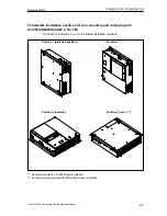
Reviews: