Hardware Information
Release 11/02
7-17
SIMATIC Panel PC 870 Computing Unit, Equipment Manual
7.5.3
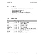
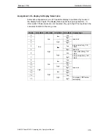
Assignment of the internal ports on the motherboard
Interface
Posi-
tion
Connec-
tor
Description
Memory
X3, X4,
X5
3 SO-DIMM sockets, 64 bit
Processor
X1
Socket for FCPGA processor
Bus expansion
X20
Socket for bus expansion, assigned with ISA and
PCI bus signals)
Power supply
X50
20-pin cable connector for power supply
Floppy
X26
Two drives are possible (82078 compatible)
360 kB, 720 kB, 1.2 MB, 1.44 MB
3F0h – 3F7h, 370h – 377h, can be disabled
IRQ 6, edge-triggered
34-pin, socket for standard floppy drive
3.5” hard disk
inter-
X7
170h-177h, 1F0h-1F7h, can be disabled
IRQ 14, IRQ 15, edge-triggered
40-pin, 2.54 mm plug connector (3.5” HD, primary);
a maximum of 2 drives is possible
CD-ROM drive
nal
X10
170h-177h, 1F0h-1F7h, can be disabled
IRQ 14, IRQ 15, edge-triggered
44-pin, 2 mm plug connector (CDROM, secondary
master);
a maximum of one drive is possible
V.24/TTY module
X28, X29
Connection for V.24/TTY hybrid (physical interface)
Power supply
connection for
CPU fan
X41
Power supply for CPU fan,
3-pin, plug connector
Power supply
connection for
device fan
X42
Power supply for device fan,
3-pin, plug connector
Backup battery
X49
Connection for backup battery,
2-pin, plug connector
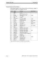
Port to bus module (X20)
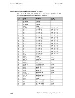
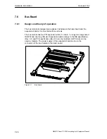
The computer unit has a bus module with a PCI expansion slot and a shared
ISA/PCI slot. Expansion boards can be installed complying with ISA specification
(Rev. 3.1) and PCI specification (Rev. 2.0) with a maximum length of 265 mm
(175 mm for shared ISA/PCI modules) (see Chapter 4). All PCI slots can be used
as masters. Only 5 V PCI modules can be operated.
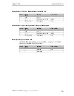
The power supply of the expansion boards runs via the connection of the bus
module to the basic board. The -5 V voltage is not provided by the power supply
and is generated from the -12 V on the bus module using in-phase control.
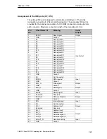
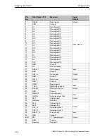
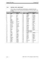
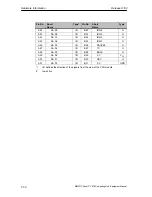
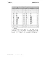
The connection to the basic board is established by a gold-plated ’EISA’ type
two-part connector. All the necessary bus signals (ISA and PCI) are applied to this
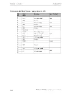
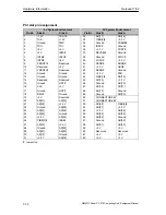
connector. The following table shows the connector pin assignment.
Summary of Contents for Simatic PC Panel PC 870
Page 4: ...Chapter For your notes ...
Page 12: ...Contents Release 11 02 xii SIMATIC Panel PC 870 Computing Unit Equipment Manual ...
Page 94: ...Fault Diagnosis Release 11 02 6 10 SIMATIC Panel PC 870 Computing Unit Equipment Manual ...
Page 130: ...Hardware Information Release 11 02 7 36 SIMATIC Panel PC 870 Computing Unit Equipment Manual ...
Page 154: ...Index Release 11 02 Index 4 SIMATIC Panel PC 870 Computing Unit Equipment Manual ...


