4-11
SIMATIC PC RI25/45, Technical Description
C79000-G7076-C808-01
4.7
Software Interfaces
The module is referenced via an I/O register. Four I/O addresses are occupied
(xxCh, xxDh, xxEh, xxFh). Only the backed-up RAM is located in the
memory-mapped area.
In order to avoid address overlaps, alternative addresses are available. These
are set by two address switches S2 and S3 (on = switch closed).
Address
switch S3
Address
switch S2
Base
addresses
Notes
on
on
220h
on
off
2A0h
off
on
320h
Standard setting
off
off
3A0h
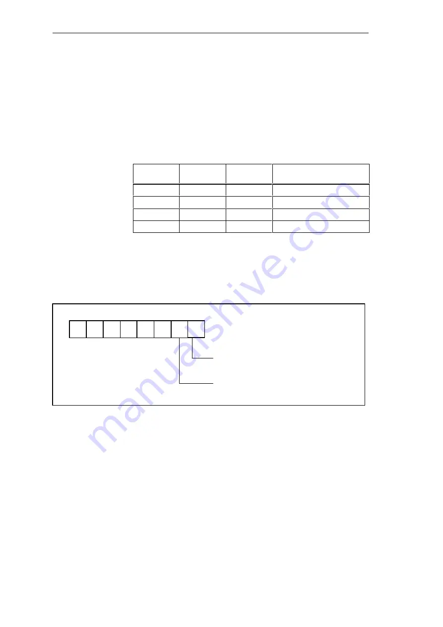
The monitoring features WD and Temp are provided by the register base
a 0Eh.
Contents of I/O cell base a 0Eh on display.
RD base a 0Eh
HSB
LSB
TEMP
0 = Temperature error, LED red
1 = OK LED green
WD
0 = WD not triggered in T
WD
,
LED=red.
1 = WD triggered, LED green
If WD is reset or not used (LED OFF) the number 1 is also indicated in this
bit.
Overview
Base Addresses
Reading Register
Base
Address
+
0Eh
Monitoring Module


