I/O configuration variants
4.1 Stand-alone operation
CPU 410-5H Process Automation
50
System Manual, 09/2014, A5E31622160-AB
What you have to take into account for stand-alone operation of a CPU 410-5H
Note the following for stand-alone operation of a CPU 410-5H:
●
In stand-alone operation of a CPU 410-5H, no synchronization modules may be
connected.
●
The rack number must be set to "0".
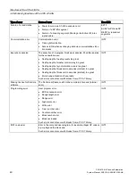
Note the different procedures described below for any system change during operation:
Table 4- 1
System modifications during operation
CPU 410-5H in stand-alone operation
CPU 410-5H in redundant system state
As described in the "System Modification during Operation
Using CIR" manual.
As described in section Failure and replacement of compo-
nents during redundant operation (Page 185) for redundant
operation.
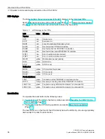
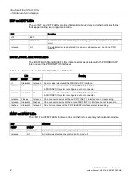
Fault tolerance-specific LEDs
The REDF, IFM1F, IFM2F, MSTR, RACK0 and RACK1 LEDs show the reaction specified in
the table below in stand-alone operation.
LED
Behavior
REDF
Dark
IFM1F
Dark
IFM2F
Dark
MSTR
Lit
RACK0
Lit
RACK1
Dark
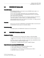
Configuring stand-alone operation
Requirement: No synchronization module may be inserted in the CPU 410-5H.
Procedure:
1.
Insert the CPU 410-5H in a standard rack (Insert > Station > SIMATIC 400 station in
SIMATIC Manager).
2.
Configure the station with the CPU 410-5H according to your hardware configuration.
3.
Assign the parameters of the CPU 410-5H. Use the default values, or customize the
necessary parameters.
4.
Configure the necessary networks and connections. For stand-alone operation you can
also configure "fault-tolerant S7 connections".
For help on procedure refer to the Help topics in SIMATIC Manager.

