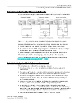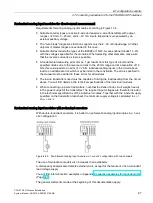
I/O configuration variants
4.7 Connecting redundant I/O to the PROFIBUS DP interface
CPU 410-5H Process Automation
System Manual, 09/2014, A5E31622160-AB
79
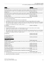
Module
Article No.
AI 8x16Bit
6ES7 331-7NF10-0AB0
Use in voltage measurement
•
The "wire break" diagnostics function in HW Config must not be activated, neither when operating the modules with
transmitters nor when thermocouples are connected.
Use in indirect current measurement
•
Use a 250 ohm resistor (measuring range 1 - 5 V) to map the current on a voltage; see figure 11-4.
Use in direct current measurement
•
Suitable Zener diode: BZX85C8v2
•
Load capability of 4-wire transmitters: R
B
> 610 ohms
(determined for worst case: 1 input + 1 Zener diode at an S7 overload value 24 mA to R
B
= (R
E
* I
max
+ U
z max
)/I
max)
•
Input voltage in the circuit when operating with a 2-wire transmitter:
U
e-2w
< 15 V (determined for worst case: 1 input + 1 Zener diode at an S7 overload value 24 mA to U
e-2w
= R
E
* I
max
+
U
z max
)
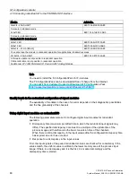
AI 6xTC 16Bit iso, 6ES7331-7PE10-0AB0
6ES7331-7PE10-0AB0
Notice: These modules must only be used with redundant encoders.
You can use this module with Version 3.5 or higher of FB 450 "RED_IN" in the library "Redundant IO MGP" and Version
5.8 or higher of FB 450 "RED_IN" in the library "Redundant IO CGP" V50.
Observe the following when measuring temperatures by means of thermocouples and assigned redundancy:
The value specified in "Redundancy" under "Tolerance window" is always based on 2764.8 °C. For example, a tolerance
of 27 °C is checked if "1" is entered, or a tolerance of 138 °C is checked if "5" is entered.
A firmware update is not possible in redundant operation.
Online calibration is not possible in redundant operation.
Use in voltage measurement
•
The "wire break" diagnostics function in HW Config must not be activated when operating the modules with thermo-
couples.
Use in indirect current measurement
•
Due to the maximum voltage range +/- 1 V, the indirect current measurement can be carried out exclusively via a 50
ohm resistor. Mapping that conforms to the system is only possible for the area +/- 20 mA.
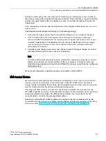
AI 4x15Bit [EEx ib]
6ES7331-7RD00-0AB0
You cannot use the module in redundant operation for applications in hazardous areas.
It is not suitable for indirect current measurement.
Use in direct current measurement
•
Suitable Zener diode: BZX85C6v2
•
Load capability of 4-wire transmitters: RB > 325 ohms
determined for worst case: 1 input + 1 Zener diode at an S7 overload value 24 mA to RB = (RE * I
max +
U
z max
)/I
max
•
Input voltage for 2-wire transmitters: Ue–2w < 8 V
determined for worst case: 1 input + 1 Zener diode at an S7 overload value 24 mA to Ue–2w = RE * I
max
+ U
z max
Note: You can only connect 2-wire transmitters with a 24 V external supply or 4-wire transmitters. The internal power sup-
ply for transmitters cannot be used in the circuit shown in figure 11-4 because it outputs only 13 V, which means in the
worst case it would supply only 5 V to the transmitter.
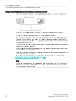
AI 8x0/4...20mA HART
6ES7 331-7TF01-0AB0
A firmware update is not possible in redundant operation.
Online calibration is not possible in redundant operation.
See Manual
ET 200M Distributed I/O Device; HART Analog Modules
manual


