Failure and replacement of components during redundant operation
11.2 Failure and replacement of components of the distributed I/Os
CPU 410-5H Process Automation
196
System Manual, 09/2014, A5E31622160-AB
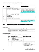
Step
What to do?
How does the system react?
5
Plug the Profibus DP back in.
–
6
Turn on the power supply of the central rack.
_
7
Switch to the CPU with the modified configuration.
The reserve CPU links up, is updated and becomes
the master. The previous master CPU switches to
STOP mode, the fault-tolerant system operates with
the new hardware configuration in single mode, see
chapter Step 5: Switch to CPU with modified configu-
8
Turn off the power supply of the second central rack. -
9
Unplug the Profibus DP cable of the second DP
master module.
–
10
Replace the module.
–
11
Plug the Profibus DP back in.
–
12
Turn on the power supply of the second central rack
again.
-
13
Perform a "Warm restart".
CPU performs a link-up and update and operates as
stand-by CPU, see chapter Step 6: Transition to
redundant system state (Page 161).
11.2.2
Failure and replacement of a redundant PROFIBUS DP interface module
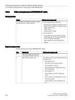
Starting situation
Failure
How does the system react?
The S7-400H is in redundant system mode and a
PROFIBUS DP interface module (IM 153–2, IM
157) fails.
Both CPUs report the event in the diagnostic
buffer and via OB 70.
Replacement procedure
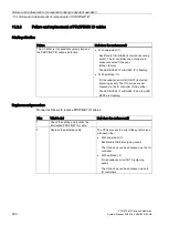
Proceed as follows to replace the PROFIBUS DP interface module:
Step
What has to be done?
How does the system react?
1
Turn off the supply for the affected DP
interface module.
–
2
Remove the bus connector.
–
3
Insert the new PROFIBUS DP interface
module and turn the power supply back on.
–
4
Plug the bus connector back in.
•
The CPUs process the I/O redundancy
error OB 70 (outgoing event) synchro-
nized with each other.
•
Redundant access to the station by the
system is now possible again.

