Description
1.2 View
PN/PN coupler
12
Installation and Operating Manual, 06/2010, A5E00717043-04
1.2
View
Display elements and interfaces
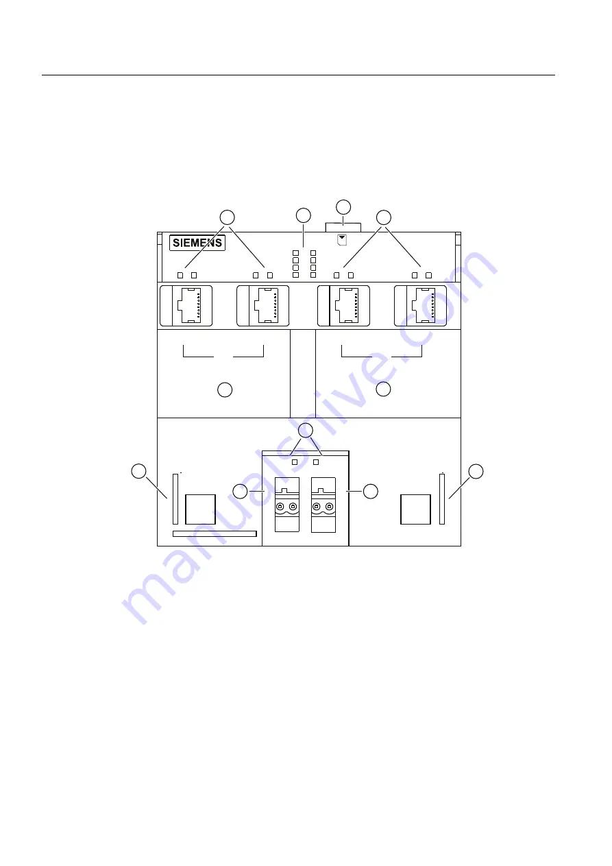
The following picture shows the PN/PN coupler and its display elements and interfaces:
3131&283/(5
/,1.
/,1.
/,1.
/,1.
5;7;
5;7;
5;7;
5;7;
386+
352),1(7
/$1
/$1
352),1(7
35
35
35
35
;
;
36
36
/
/
0
0
'&9
0$&
0$&
$''
$''
%)
6)
07
21
;
;
①
PROFINET IO interfaces for subnet 1 (X1)
⑥
Status LEDs for PROFINET IO subnet 1 (X1)
②
PROFINET IO interfaces for subnet 2 (X2)
⑦
Status LEDs for PROFINET IO subnet 2 (X2)
③
Status-LEDs for connection of the electrical
supply PS1 / PS2
⑧
MAC address for PROFINET IO subnet 1 (X1)
④
DC24V electrical supply PS1 / PS2
(X20 / X21)
⑨
MAC address for PROFINET IO subnet 2 (X2)
⑤
Diagnostics LEDs for PROFINET IO subnet
1 and 2 (X1, X2)
⑩
Slot for SIMATIC Micro Memory Card
Figure 1-5
Display elements and interfaces of the PN/PN coupler


