Mounting, connecting up and commissioning
3.2 Installing and commissioning the RF120C
Communications module RF120C with application blocks for S7-1200 and S7-1500
Operating Instructions, 07/2013, C79000-G8976-C328-01
15
Table 3- 2
Installing and connecting up an RF120C
Task
Procedure
1.
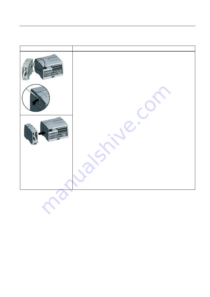
Remove the bus cover on the left of the CPU:
–
Insert a screwdriver into the slot above the bus cover.
–
Lever the cover up carefully out of its mounting.
Remove the bus cover. Put the cover away for later use.
2.
Connect the RF120C to the CPU:
–
Align the bus connector and the pins of the RF120C with the drill holes in the
CPU.
–
Press the components together firmly until the limit stop is reached.
3.
Fit the CPU with the connected modules onto the 35 mm DIN rail and secure the
DIN rail.
4.
Secure the power supply wires to the external power supply unit.
5.
Secure the wires of the external power supply to the plug supplied with the
RF120C and insert the plug in the socket on the top of the RF120C.
The pinning is shown beside the socket on the top of the housing. You will also
find this in the section "Pin assignment of the socket for the external power supply
(Page 20)".
6.
Connect the reader using the RF120C cable to the D-sub female connector of the
RF120C. To do this, open the lower door in the housing.
7.
Turn on the power supply.
8.
Close the front covers of the module and keep them closed during operation.
9.
The remaining steps in commissioning involve downloading the STEP 7 project
data.
The STEP 7 project data of the RF120C is transferred when you download to the
station. To load the station, connect the engineering station on which the project data
is located to the Ethernet interface of the CPU.
You will find more detailed information on loading in the following sections of the
STEP 7 online help:
•
"Loading project data"
•
"Using online and diagnostics functions"


