SIMATIC RF185C, RF186C, RF188C, RF186CI, RF188CI
Operating Instructions, 04/2020, C79000-G8976-C512-03
111
Programming via SIMATIC controller
8
This section is intended only for S7 users.
You can program and configure the SIMATIC RF185C, RF186C, RF188C as well as the
RF186CI and RF188CI communication modules using Ident instructions via a SIMATIC
controller.
To configure Ident systems using STEP 7 Basic / Professional (TIA Portal), you need
appropriate Ident instructions. The Ident profile and the Ident blocks are integrated in STEP
7 as of version V13.1.
You can find a detailed description of the Ident profile and the Ident blocks in the "Ident
profile and Ident blocks, standard function for Ident systems
https://support.industry.siemens.com/cs/ww/en/view/109762333
)" function manual.
8.1
Digital inputs/outputs
The RF18xCI communication modules have configurable digital inputs/outputs that you can
configure using the WBM. You will find more information on this in the section "The "Settings
- Digital outputs" menu item (Page 78)".
You can operate the interface as a single input (DI 0) or a single output (DO 0 and PI 0), as
needed, or you can connect an IO-Link module. IO-Link modules with up to 8 inputs and/or 8
outputs are supported.
The inputs/outputs are mapped in a data word each in the process image of the controller.
Because the physical output value of the CM can deviate from the process image value of
the controller through internal linking, each physical output value is also mapped as
additional input in the controller.
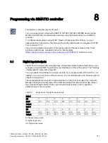
Table 8- 1
Assignment of the digital inputs/outputs
Byte 1
Bit
7
6
5
4
3
2
1
0
Input
PI 7
PI 6
PI 5
PI 4
PI 3
PI 2
PI 1
PI 0
Output
--
--
--
--
--
--
--
--
Byte 0
Bit
7
6
5
4
3
2
1
0
Input
DI 7
DI 6
DI 5
DI 4
DI 3
DI 2
DI 1
DI 0
Output
DO 7
DO 6
DO 5
DO 4
DO 3
DO 2
DO 1
DO 0
PI: Physical output value
DI: Digital input value
DO: Digital output value

