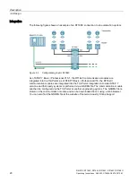
Description
3.4 Design
SIMATIC RF185C, RF186C, RF188C, RF186CI, RF188CI
Operating Instructions, 04/2020, C79000-G8976-C512-03
19
Orientation in the document
Later in the document, these symbols will help your orientation and will show you whether
the section is of interest to you or not. Only the sections with user-specific content, in other
words, content that is interface-specific, contain these symbols. Sections without these
symbols are general and relevant for all areas of application.
3.4
Design
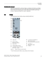
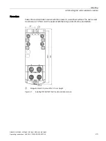
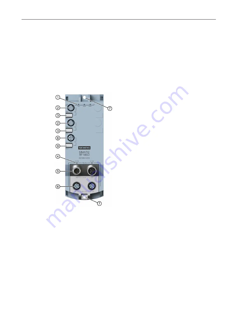
The following figure shows the basic design of the RF18xC/RF18xCI.
①
Status LEDs
⑥
2x interfaces for PROFINET IO
(M12, 4-pin, D-coded)
②
Reader interfaces
(M12, 8-pin, A-coded)
⑦
Mounting holes and functional ground
③
Reader LEDs
⑧
I/O interface
1)
(M12, 5-pin, A-coded)
④
PROFINET/Ethernet LEDs
⑨
IO LEDs
1)
⑤
2x interfaces for the power supply
(M12, 4-pin, L-coded)
Figure 3-2
Design of the communication module
1)
The I/O interface and I/O-LEDs are only a feature of the CI devices.

