
SIMATIC RF185C, RF186C, RF188C, RF186CI, RF188CI
Operating Instructions, 04/2020, C79000-G8976-C512-03
47
Configuring
6
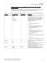
Synchronize device time
Note that the time of the device clock corresponds to UTC time and cannot be adjusted to
time zones. It is recommended to synchronize the time with an NTP server to obtain unique
time information. The time is reset with a device restart and must be synchronized.
6.1
Assign the IP address / device name
To ensure functioning communication between the controller and the communication
module, you must assign unique IP addresses or device names to the individual
communication modules. Depending on the infrastructure in which you want to operate the
communication module, the following different procedures are available:
●
Operate the communication module as an S7 user in an automation environment.
The unique assignment is made via the device name using the TIA Portal (from STEP 7
Basic / Professional V15).
●
Operate the communication module as XML or OPC UA user in an IT environment.
The unique assignment is based on DHCP or the IP address using SINEC PNI.
●
Operate the communication module as a Rockwell user (EtherNet/IP) in an automation
environment.
The unique assignment is made with the IP address using a DHCP server.
Each communication module receives a unique device identification (MAC address) at the
factory.
6.1.1
Assigning the IP address / device name with STEP 7
Requirements
STEP 7 Basic / Professional is installed, the communications module is connected and has
started up.
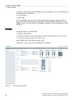
Procedure
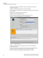
Proceed as follows to assign a unique device name to the communications module:
1.
Open the TIA Portal with "Start > All Programs > Siemens Automation > TIA Portal Vxx".
2.
Create a new project.
3.
Change to the Project view.


